16 ENGINE 131
300159-10
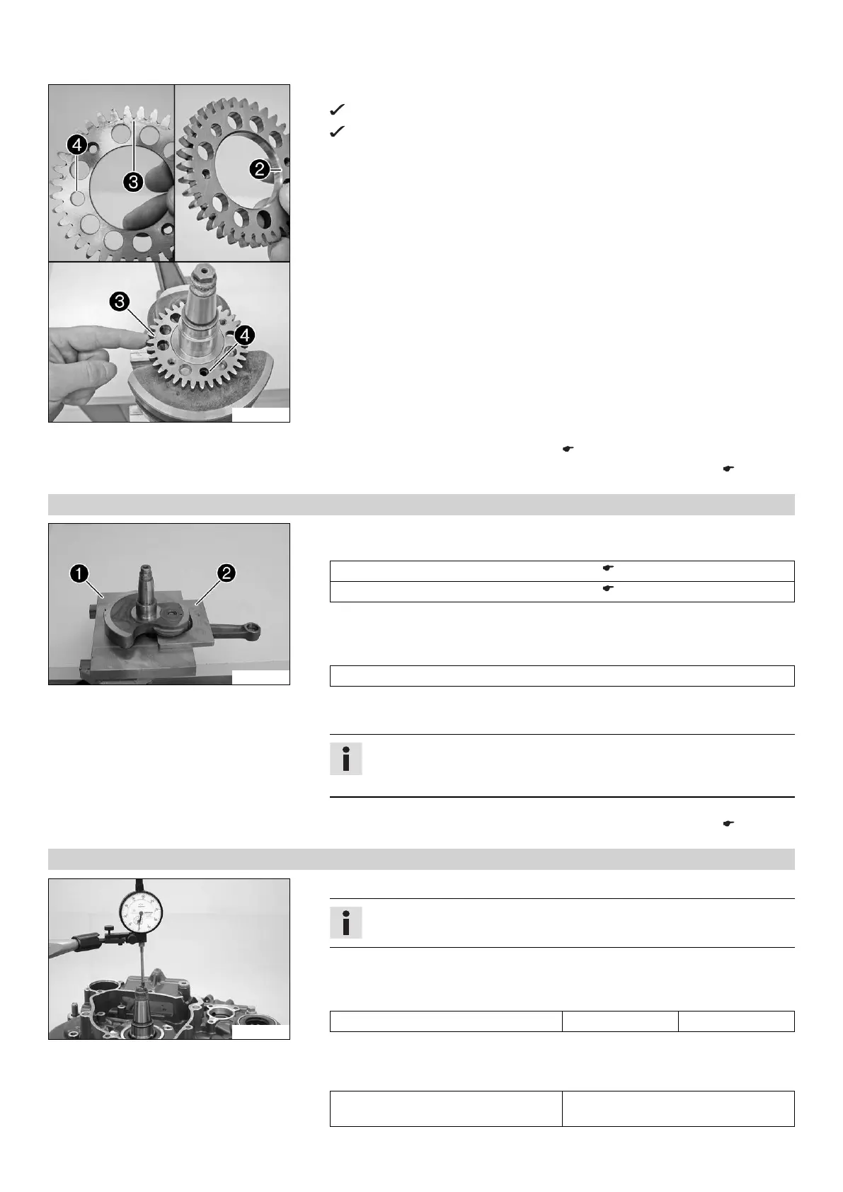
– Place the drive wheel on the crankshaft.
The dowel of the crankshaft must fit in the drill hole
.
The side of the drive wheel with the punch mark
must be visible after
assembly, and the side with the bevel
must be in contact with the
crankweb.
Finishing work
– Install the crankshaft bearing inner ring. ( p. 131)
– Measure the axial clearance of the crankshaft and the balancer shaft. ( p. 131)
16.4.9 Installing crankshaft bearing inner ring
302150-10
Main work
–
Fix the crankshaft with special tools
and
in the vise.
Upper part, pressing-out tool (75029047050) ( p. 234)
Under part, pressing-out tool (75029047051) ( p. 235)
– Push on the compensation shim.
– Heat the special tool. Install the inner bearing race.
Guideline
120 °C (248 °F)
– Repeat the operation on the opposite side.
– Make sure that the new inner bearing race is installed flush.
Info
After changing the crankshaft bearing and the conrod bearing, measure the
axial play of the crankshaft.
Finishing work
– Measure the axial clearance of the crankshaft and the balancer shaft. ( p. 131)
16.4.10 Measuring axial clearance of crankshaft and balancer shaft
300126-10
– Insert the crankshaft and balancer shaft in the right engine casing.
Info
Do not forget the dowels.
– Mount the left engine casing.
– Mount and tighten the screws.
Guideline
Screw, engine case M6 10 Nm (7.4 lbf ft)
– Mount the dial gauge support on the engine case and measure and note the axial
clearance of the crankshaft.
Guideline
Crankshaft - axial clearance 0.15… 0.25 mm (0.0059…
0.0098 in)

 Loading...