16 ENGINE 163
305568-10
–
Position the timing chain guide rail
from above.
– Insert the support bushing into the timing chain securing guide.
–
Mount and tighten screws
.
Guideline
Screw, timing chain guide
rail
M6x30 10 Nm
(7.4 lbf ft)
Loctite
®
243™
Screw, timing chain ten-
sioning rail
M6x30 10 Nm
(7.4 lbf ft)
Loctite
®
243™
Info
Ensure that there is no thread locking material at the collar of the screw;
otherwise, the timing chain tensioning rail could lock and break.
– Check both timing chain rails for freedom of movement.
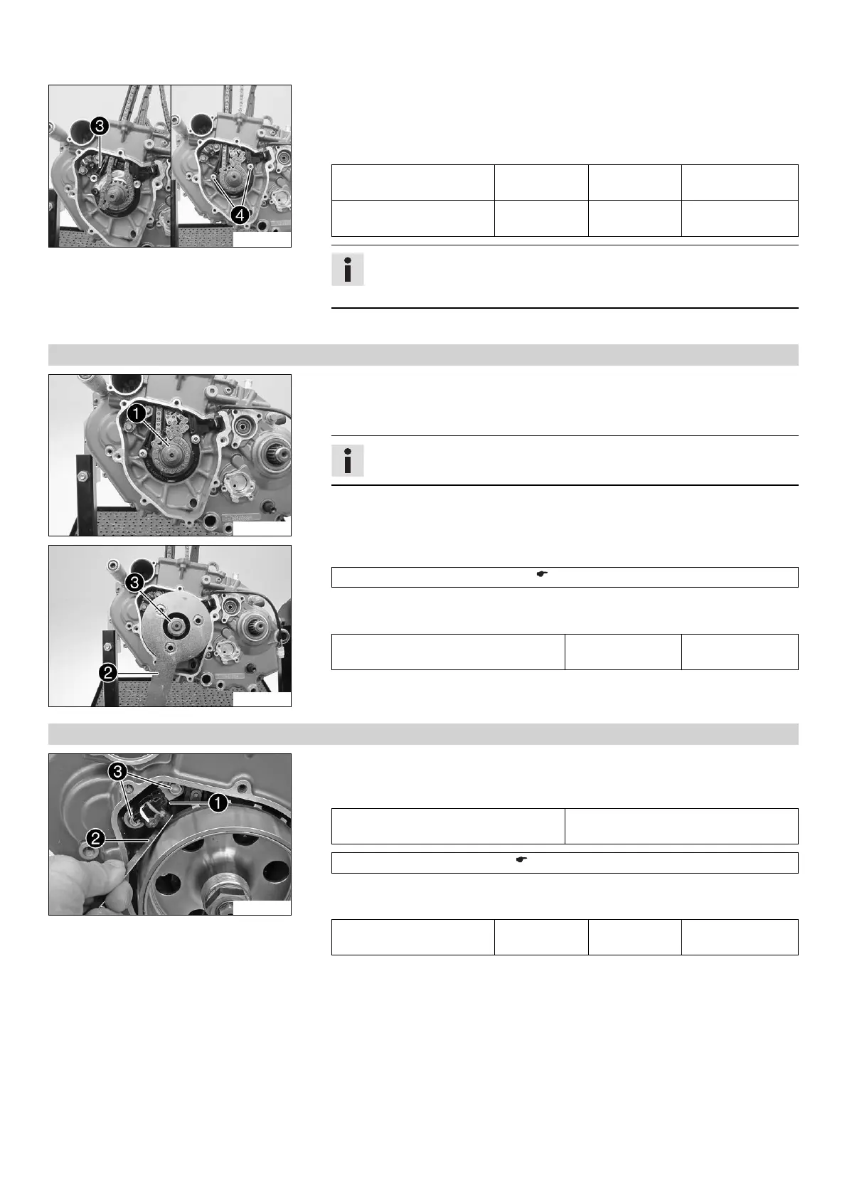
16.5.16 Installing the rotor
305563-10
–
Ensure that woodruff key
is seated properly.
– Degrease the cone of the crankshaft and rotor.
– Mount the rotor.
Info
Make sure that the crankshaft is not blocked.
305561-10
–
Hold the rotor with special tool
.
Holding spanner (75029091000) ( p. 236)
–
Mount and tighten nut
with the locking edge washer.
Guideline
Rotor nut M18x1.5 100 Nm
(73.8 lbf ft)
16.5.17 Adjusting crankshaft position sensor distance
305564-10
–
Adjust the distance between the crankshaft position sensor
and the conductive
element of the rotor using the special tool
.
Guideline
Crankshaft position sensor/rotor -
distance
0.70 mm (0.0276 in)
Feeler gauge (59029041100) ( p. 230)
–
Fully tighten screws
.
Guideline
Screw, crankshaft position
sensor
M6x16 10 Nm
(7.4 lbf ft)
Loctite
®
243™

 Loading...