16 ENGINE 156
305644-10
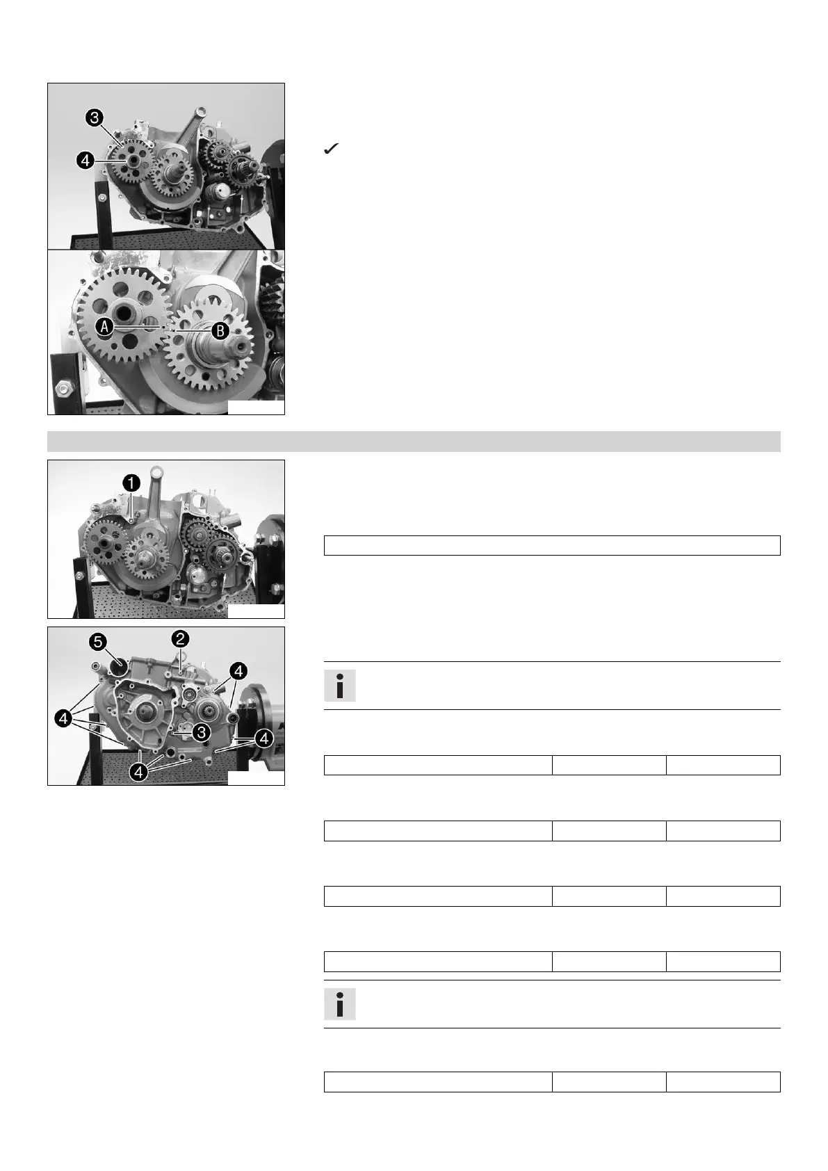
– Push the crankshaft into the bearing seat and take off the special tool.
– Grease the shaft seal rings of the balancer shaft.
–
Push the balancer shaft
into the bearing seat and take off the special tool.
Align marks
and
.
–
Mount stop disk
.
16.5.3 Installing the left engine case
305635-10
– Mount the dowels.
–
Mount O-ring
.
– Degrease the sealing area. Apply the sealing compound to the left section of the
engine case.
Loctite
®
5910
305636-10
– Put on the left section of the engine case. If necessary, tap lightly with a rubber
mallet and turn the transmission shafts.
Info
Do not tighten the engine case sections using the screws.
–
Mount screw
but do not tighten it yet.
Guideline
Screw, engine case M6x80 10 Nm (7.4 lbf ft)
–
Mount screw
but do not tighten it yet.
Guideline
Screw, engine case M6x70 10 Nm (7.4 lbf ft)
–
Mount screws
but do not tighten yet.
Guideline
Screw, engine case M6x30 10 Nm (7.4 lbf ft)
–
Mount screw
with washer but do not tighten it yet.
Guideline
Screw, engine case M6x25 10 Nm (7.4 lbf ft)
Info
Mount the screw with a new copper washer.
– Tighten all screws in a crisscross pattern.
Guideline
Screw, engine case M6 10 Nm (7.4 lbf ft)

 Loading...