EasyManua.ls Logo

Lenze i55AE155F User Manual

Lenze i55AE155F
702 pages
To Next Page IconTo Next Page
To Previous Page IconTo Previous Page
Page #586 background imageLoading...
Page #586 background image
Example for operang mode
In the following example, the "Deacvate PID controller" funcon is used to deacvate the
PID control temporarily:
As standard setpoint source, the frequency preset 1 is set to 20 Hz.
Switch S1 starts the motor in forward direcon of rotaon. Switch S1 in the inial posion
stops the motor again.
Switch S2 deacvates the PID control. The motor is then driven in a speed-controlled way.
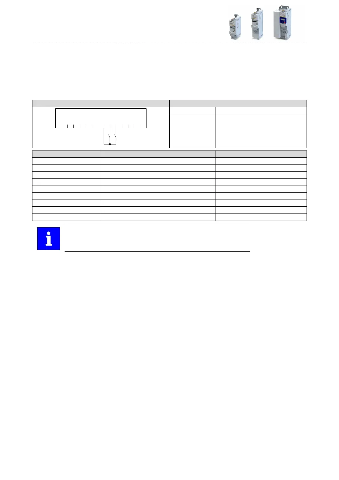
Connecon plan funcon
GND
AI1
AI2
AO1
10V
24V
DI1
DI2
DI3
DI4
DI5
DO1
X3
S1 S2
Switch S1 Run
Switch S2 Deacvate PID controller
Parameter Name Seng for this example
0x2631:001 (P400.01) Enable inverter Constant TRUE [1]
0x2631:002 (P400.02) Run Digital input 1 [11]
0x2631:004 (P400.04) Reset fault Not connected [0]
0x2631:045 (P400.45) Deacvate PID controller Digital input 2 [12]
0x2824 (P200.00) Control selecon Flexible I/O conguraon [0]
0x2838:003 (P203.03) Stop method Standard ramp [1]
0x2860:001 (P201.01) Frequency control: Default setpoint source Frequency preset 1 [11]
0x2911:001 (P450.01) Frequency setpoint presets: Preset 1 20 Hz
0x2916 (P211.00) Maximum frequency 50 Hz
The example assumes that the process controller has been congured accord-
ingly. 4Conguring the process controller ^ 407
Flexible I/O conguraon
Process controller funcon selecon
586

Table of Contents

Questions and Answers:

Lenze i55AE155F Specifications

General IconGeneral
BrandLenze
Modeli55AE155F
CategoryInverter
LanguageEnglish

Summary

General Information

Read First, Then Start

Provides essential starting guidance and safety instructions before proceeding with installation and commissioning.

Safety Instructions

Basic Safety Measures

Outlines fundamental safety precautions to prevent severe personal injury and material damage.

Electrical Installation

Connection of the Safety Module

Describes the connection of the safety module, including critical warnings about automatic restart.

Commissioning

Important Notes

Provides critical warnings about incorrect wiring and settings during commissioning, emphasizing safety checks.

Save Parameter Settings in the Memory Module

Details how to save parameter settings using the keypad or the EASY Starter software for mains failure protection.

Diagnostics and Fault Elimination

LED Status Display

Explains the meaning of "RDY" and "ERR" LEDs on the inverter for quick information on operating states.

Error Handling

Discusses how the inverter detects errors, protects components, and handles operating errors, warnings, and faults.

Data Handling

Describes inverter behavior when memory module data does not match hardware or firmware, covering automatic and manual loading/saving.

Basic Setting

Mains Voltage

Explains how the rated mains voltage impacts the inverter's operating range and provides a table of settings.

Starting/Stopping Performance

Covers starting performance options like DC braking or flying restart circuit, and stopping performance methods like coasting or quick stop.

Quick Stop

Describes the "quick stop" function as an alternative stop method for faster motor stopping, including its triggers and parameters.

Motor Control

Motor Data

Explains how to set motor data manually, covering parameters like pole pairs, rated speed, frequency, power, and current.

Motor Control Selection

Details the different modes for closed-loop/open-loop motor control supported by the inverter.

Optimisation of Motor Control

Covers functions for further optimizing drive behavior, including V/f voltage boost, skip frequencies, and oscillation damping.

Optimisation of the Control Loops

Covers options for improving total system power by selecting motors, tuning controllers, and performing automatic identification/calibration.

Motor Protection

Covers various monitoring functions to protect the device or motor from destruction or overload.

Configuring the Network

General Network Settings

Covers activating network control, network control words, status words, and data mapping for network registers.

Configuring the Process Controller

Basic Process Controller Settings

Details basic settings for PID control, including activating PID, configuring analog inputs, and selecting setpoint sources.

Additional Functions

Device Commands

Covers device commands for calling organizational functions like saving, loading, and resetting parameter settings.

DC Braking

Details the DC braking function, which generates braking torque by injecting DC current into the motor.

Access Protection

Covers write access protection for inverter parameters via keypad and EASY Starter, restricting parameterization.

Mains Failure Control

Explains the function that decelerates the motor during power failure using rotational energy to maintain DC-bus voltage.

Safety Functions

Safe Torque Off (STO)

Explains the STO function for safely switching off the drive immediately and its operating principle.

Flexible I/O Configuration

Control Source Change-over

Details how to configure the start, stop, and reversal commands flexibly via digital inputs, keypad, or network.

Start / Stop Motor

Covers configuration of triggers for basic motor functions like enable, run, quick stop, and reverse.

Setpoint Change-over

Explains how to change setpoint sources during operation using functions like analog inputs, keypad, network, presets, and MOP.

Reset Error

Explains how to reset an active error by using the "Reset Fault" function or cancelling the start command.

Related product manuals