Multi-function Compact Inverter 3G3MX2-EV2 User’s Manual (I666-E1)
5-3 Motor Parameter Settings
5-3-1 Motor Capacity/Pole Number Selection
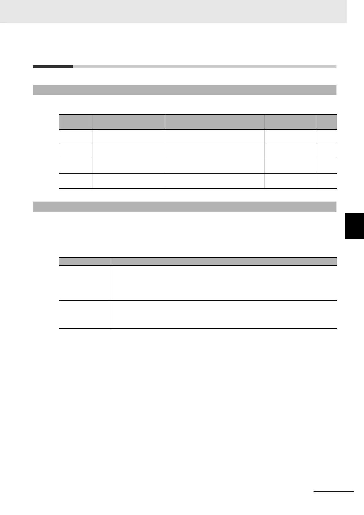
Set the following parameters according to your motor.
0.1/0.2/0.4/0.55/0.75/1.1/1.5/2.2/3.0/
3.7/4.0/5.5/7.5/11.0/15.0/18.5
Maximum applica-
ble motor capacity
0.1/0.2/0.4/0.55/0.75/1.1/1.5/2.2/3.0/
3.7/4.0/5.5/7.5/11.0/15.0/18.5
Maximum applica-
ble motor capacity
2/4/6/8
10 to 48: Do not set.
2/4/6/8
10 to 48: Do not set.
5-3-2 Electronic Thermal Function
The electronic thermal function prevents the motor from overloading and burning.
Set the rated current of your motor in the Electronic Thermal Level parameters.
In the Electronic Thermal Characteristics Selection parameters, set the motor torque characteristics as
follows, according to the motor specifications.
Reduced torque
characteristics
Use this setting for general-purpose motors.
In an air-cooled motor that uses the rear fan coupled directly to the motor shaft, the cooling
effect degrades as the motor rotation speed decreases. This characteristics setting enables
overload detection that takes into account such degradation of the cooling effect at low
speeds.
Constant torque
characteristics
Use this setting for dedicated inverter motors.
Dedicated inverter motors are designed to prevent degradation of the cooling effect that
arises as the motor speed increases. This characteristics setting provides overload detec-
tion independent of the motor rotation speed.
Derating of the output current is required depending on the installation environment and the Carrier Fre-
quency (b083). For derating of each inverter model, refer to A-1 Derating on page A-2.
In the Electronic Thermal Level, set the output current value to be derated.
This setting is, however, unnecessary if the Electronic Thermal Level is already set to the derating
value or lower.
5-3 Motor Parameter Settings
5-3-1 Motor Capacity/Pole Number Selection
 Loading...


