Multi-function Compact Inverter 3G3MX2-EV2 User’s Manual (I666-E1)
2-3-2 Arrangement and Function of Main Circuit Terminal Block
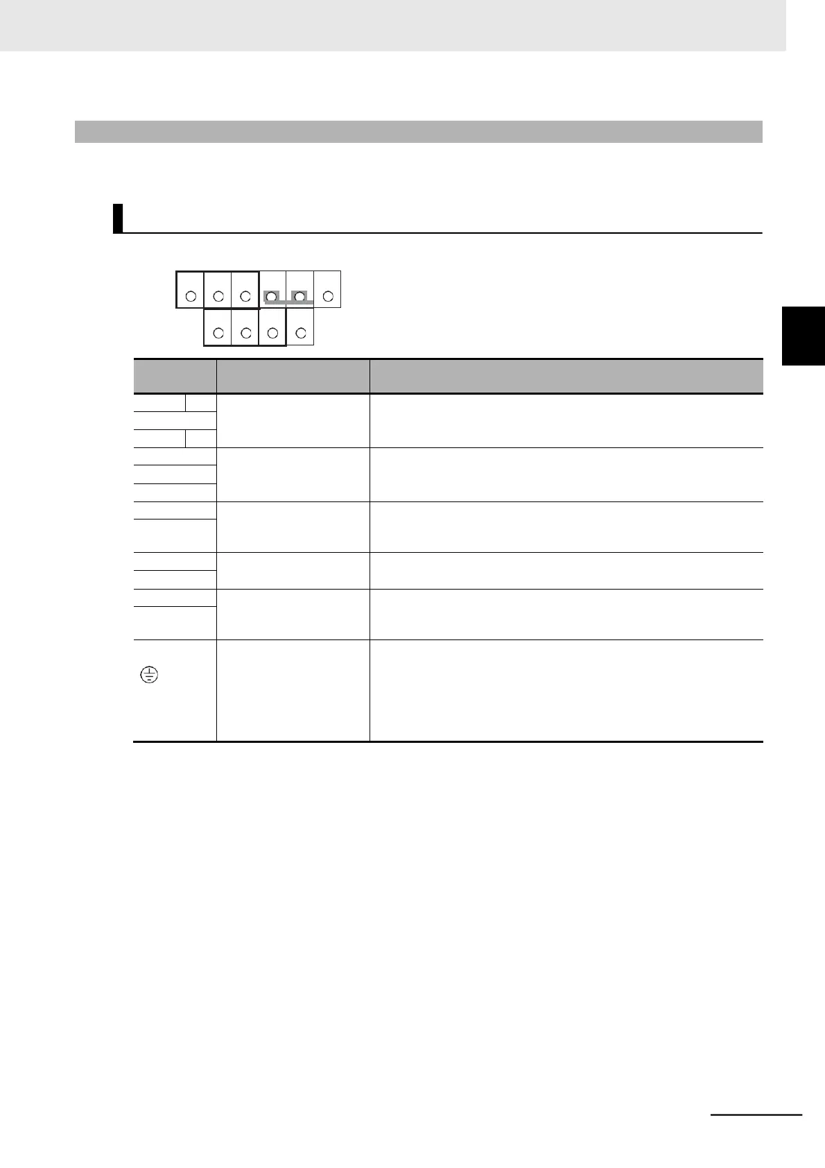
The table below shows the arrangement of the main circuit terminal block and description of each terminal.
The terminal arrangement shown on the left is an example
for the inverters with a capacity of 4.0 kW or lower.
Main power supply input
terminal
Connect the DC input power supply.
For single-phase 200-V type Inverters (Model: 3G3MX2-AB-EV2),
connect these to the L1 and N terminals, respectively.
DC reactor connection
terminal
Remove the short-circuit bar between the terminals +1 and P/+ (for
switching the inverter’s built-in filter function) and connect an optional
DC reactor.
Braking resistor connec-
tion terminal
Connect an optional braking resistor (if a braking torque is required).
Braking unit connection
terminal
Connect optional braking units (if a braking torque is required and that
produced by the built-in braking circuit is insufficient).
This is the ground terminal. Connect this terminal to the ground.
200-V class should be connected under type-D grounding conditions;
400-V class should be connected under type-C grounding conditions.
For 200-V class models with a capacity of 3.7 kW or lower and 400-V
class models with a capacity of 4.0 kW or lower, the ground terminal
is located on the cooling fin.
2-3-2 Arrangement and Function of Main Circuit Terminal Block
Main Circuit Terminal Block
 Loading...


