Multi-function Compact Inverter 3G3MX2-EV2 User’s Manual (I666-E1)
5-10-3 Multi-function Output ON/OFF Delay Time
•
Each multi-function output terminal can be allocated with the ON/OFF delay time independently.
•
Because all output signals turn ON/OFF immediately when the set conditions are met, depending on
the selected signal, chattering may occur. In such a case, use this function to hold or delay the signal.
•
Set the parameter independently for each output terminal.
For the output terminal, multi-function output terminals 11 and 12 and a multi-function relay output
(AL1, AL2) terminal are provided.
The correspondence between each output terminal and the related ON/OFF delay parameter is
shown in the table below.
Multi-function Output 11 ON Delay Time
Multi-function Output 12 ON Delay Time
Multi-function Relay Output ON Delay
Multi-function Output 11 OFF Delay Time
Multi-function Output 12 OFF Delay Time
Multi-function Relay Output OFF Delay
5-10-4 Signal during RUN (RUN)
•
The RUN signal is output during inverter operation.
•
Allocate one of the Multi-function Output 11 Selection or Multi-function Output 12 Selection
(C021/C022), or Multi-function Relay Output (AL1, AL2) Function Selection (C026), to 00
(RUN).
•
The RUN signal is also output when the inverter is decelerating after the RUN command turns OFF
or DC injection braking is active.
•
The RUN signal will not be output even if the RUN command is input when the frequency reference is
0 Hz and the output reference reaches 0 Hz. (Note that on the Digital Operator, the RUN LED is lit
when the RUN command is ON. If the set frequency is 0 Hz, it will blink.)
Multi-function Output 11/12 Selection
00: RUN (Signal dur-
ing RUN)
Multi-function Relay Output (AL1, AL2)
Function Selection
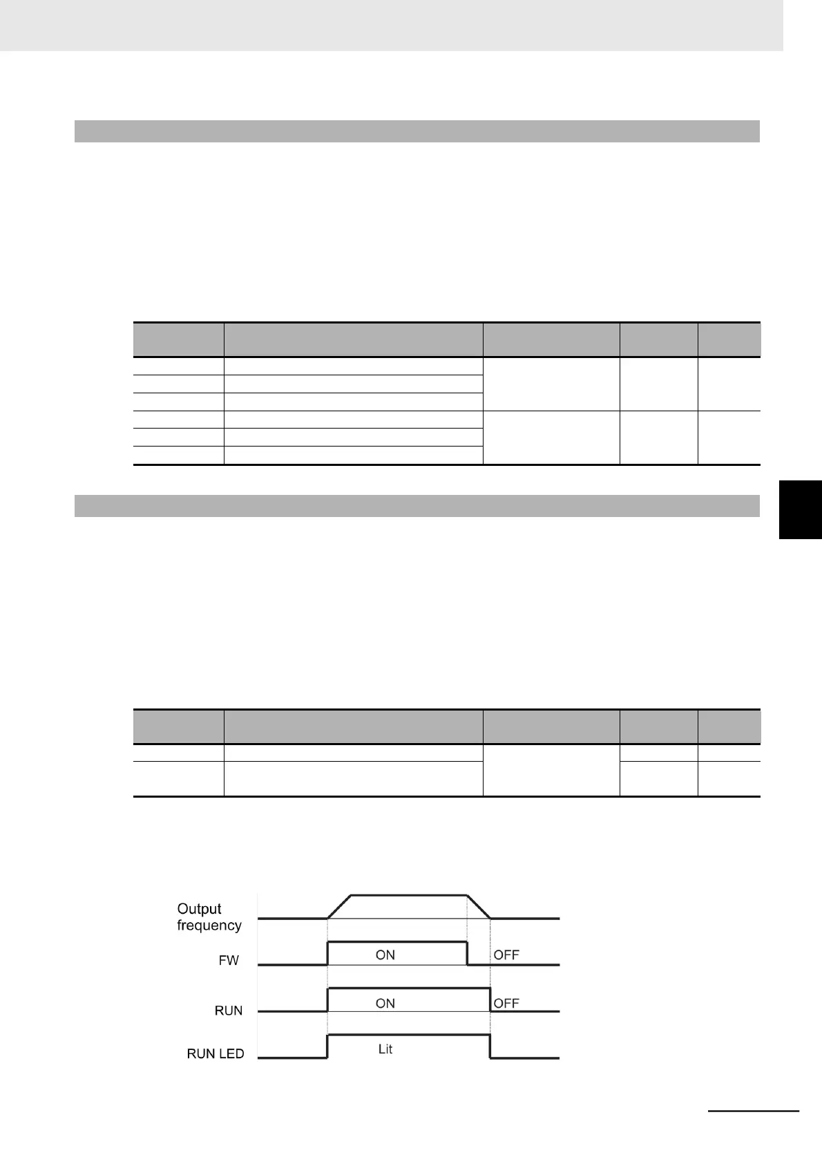
The timing diagram is as follows.
The inverter outputs the RUN (during RUN) signal until the motor is stopped even if the RUN command
(FW) turns OFF.
5-10 Multi-function Output Settings
5-10-3 Multi-function Output ON/OFF Delay Time
 Loading...


