7-1-29 Fault Monitor 1 to 6 [d081 to 086]
Use these functions to display the fault history of the last six faults. This count value will be stored to the
inverter’s EEPROM when the power supply is turned OFF.
The latest fault history is displayed in the Fault Monitor 1 (d081).
⚫
Displayed items
(1)
Trip fault factor (Alarm code): Displays one of E01 to E99.
Refer to 10-1-2 Alarm Code List on page 10-4.
(2)
Output frequency at trip [Hz]
(3)
Output current at trip [A]
The monitor value may become zero when the inverter is in a stop state (E**.1)
(4)
DC voltage between P and N in main circuit at trip [V]
The monitor value may become zero if a ground-fault trip occurs when the power supply is
turned on.
(5)
Total RUN time of inverter before trip [h]
(6)
Total power ON time of inverter before trip [h]
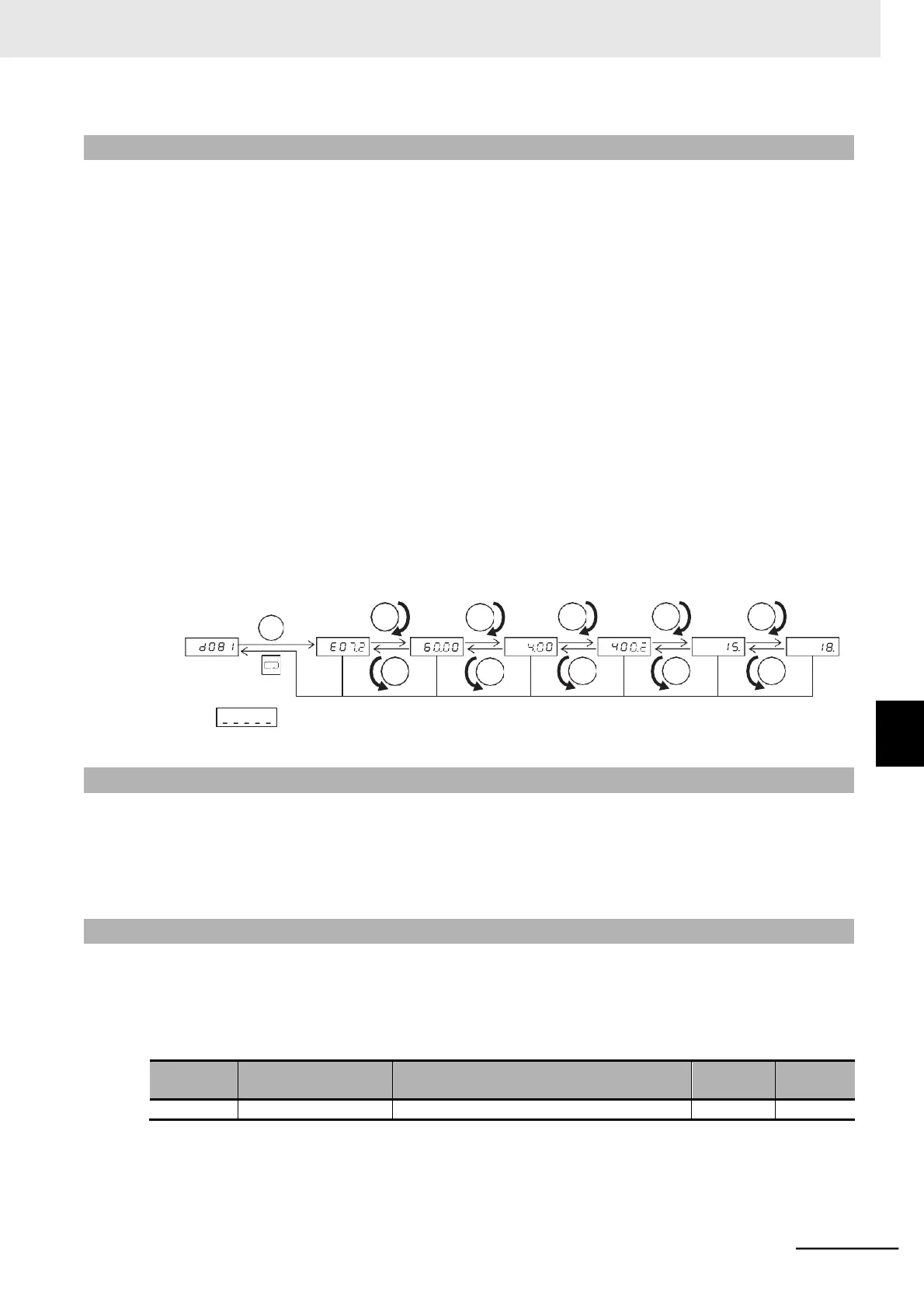
(1)
Trip
factor
(2)
Frequency
(3) Current
(4) Main
circuit
DC
voltage
(5) Total
RUN time
(6) Total power
ON time
Displays if there is no trip.
7-1-30 Warning Monitor [d090]
Use this function to display the warning code if any inconsistency is found among the set data.
The program LED indicator (PRG) blinks during the warning, until the inconsistent data is corrected.
For details on the warning display, refer to 10-1-4 Warning Display on page 10-11.
7-1-31 DC Voltage Monitor [d102]
Use this function to display the main circuit DC voltage of the inverter (main circuit DC voltage between
the P/+ and N/- terminals of the inverter.)
During operation, the monitor value changes according to the actual main circuit DC voltage of the
inverter.
 Loading...


