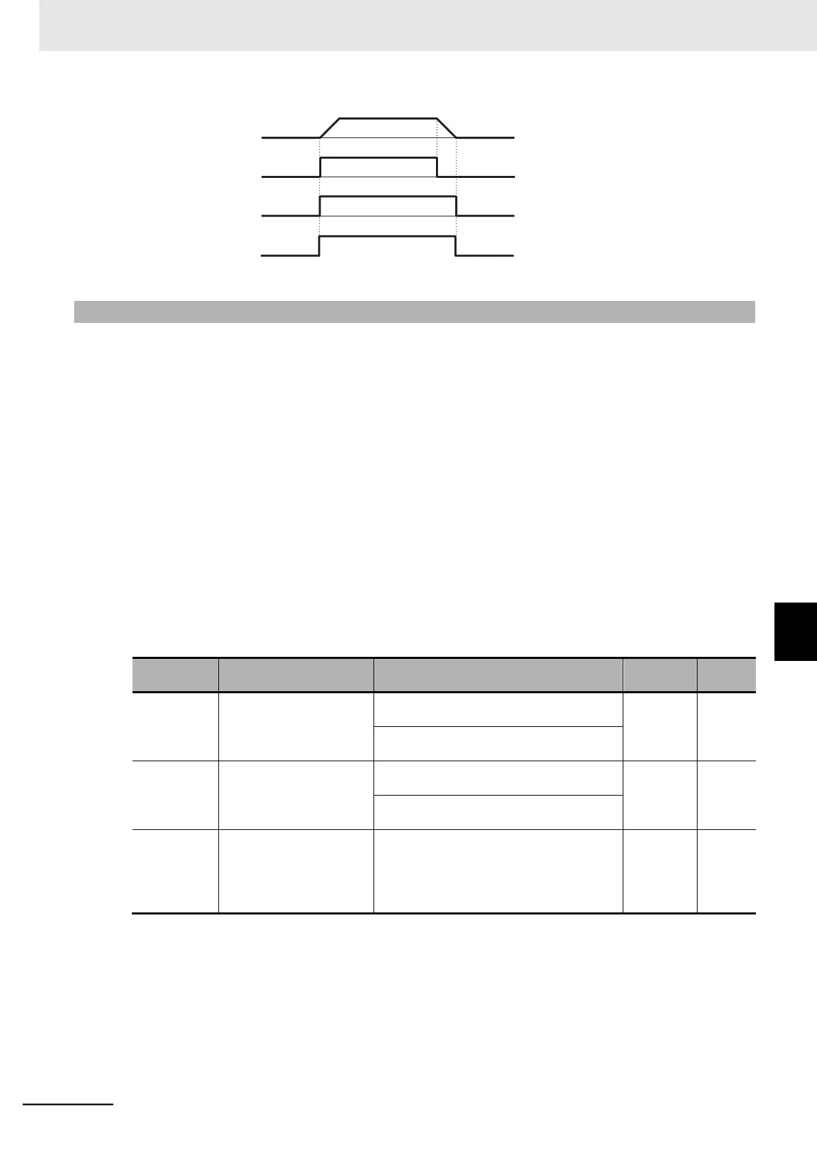
Output frequency
FW input (Forward)
RUN output
RUN LED
7-8-9 Frequency Arrival Signal (FA2 to FA5)
The inverter outputs the frequency arrival signal when the output frequency reaches the set level.
Allocate the Multi-function Output 11/12 Selection (C021/C022) or Multi-function Relay Output (AL1,
AL2) Function Selection (C026) to 02 (FA2: Set frequency exceeded signal), 06 (FA3: Set frequency
only signal), 24 (FA4: Set frequency exceeded signal 2) or 25 (FA5: Set frequency only signal 2).
The hysteresis of the signals FA2 (02) and FA4 (24) is calculated as follows.
ON : (Set frequency) − (1% of maximum frequency) [Hz]
OFF : (Set frequency) − (2% of maximum frequency) [Hz]
The hysteresis of the signals FA3 (06) and FA4 (25) during acceleration is calculated as follows.
ON : (Set frequency) − (1% of maximum frequency) [Hz]
OFF : (Set frequency) + (2% of maximum frequency) [Hz]
The hysteresis of these signals during deceleration is calculated as follows.
ON : (Set frequency) + (1% of maximum frequency) [Hz]
OFF : (Set frequency) − (2% of maximum frequency) [Hz]
02: FA2 (Set frequency exceeded signal)
06: FA3 (Set-frequency only signal)
24: FA4 (Set frequency exceeded signal 2)
25: FA5 (Set-frequency only signal 2)
 Loading...


