Multi-function Compact Inverter 3G3MX2-EV2 User’s Manual (I666-E1)
7-8-7 Thermistor Trip Function
You can provide thermal protection for external equipment such as a motor by connecting a thermistor
installed on it to the inverter and enabling this function.
Connect a PTC thermistor to the inverter. If the resistance of the PTC thermistor becomes approxi-
mately 3 k or more, the inverter will trip (E35).
To have the inverter trip at lower than 3 k, increase the Thermistor Adjustment (C085) value. Con-
versely, to have the inverter trip at higher than 3 k, decrease the C085 value.
Connect the external thermistor between the control terminals 5 and L and set the Multi-function
Input 5 Selection (C005) to 19 (TH: PTC thermistor thermal protection).
Then, set the adjustment parameter according to the specifications of the thermistor.
When using this function, keep the wiring distance between the motor and the inverter at 20 m or shorter.
Since the current flowing through the thermistor is weak, take measures, such as isolating the thermis-
tor cable, to prevent noise due to the motor current.
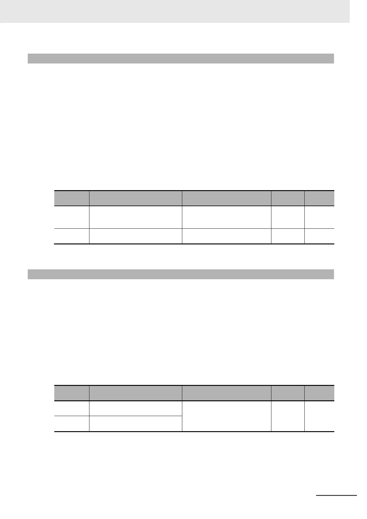
0.0 to 200.0
Fine-tune the gain relative to the
input voltage.
Multi-function Input 5 Selection
19: TH (PTC thermistor thermal
protection)
Note If no thermistor is connected when C005 is set to 19, a trip will occur.
7-8-8 Signal during RUN (RUN)
The RUN signal will be output from a multi-function output terminal or the multi-function relay output ter-
minal during inverter operation.
This signal turns ON only with the inverter output. The RUN signal is not output even if the RUN com-
mand is input when the frequency is set to 0 Hz. (When the RUN command is input, the RUN LED indi-
cator on the Digital Operator lights. The indicator blinks when the Inverter is operating at 0 Hz.)
Allocate the Multi-function Output 11/12 Selection (C021/C022) or the Multi-function Relay Output (AL1,
AL2) Function Selection (C026) to 00 (RUN: Signal during RUN).
This signal is also output when DC injection braking is active.
The timing diagram is as follows. The RUN signal remains ON until the motor stops even if the RUN
command (FW) turns OFF.
Multi-function Output 11/12
Selection
00: RUN (Signal during RUN)
Multi-function Relay Output (AL1,
AL2) Function Selection
 Loading...


