*1. Broadcasting cannot be performed.
0003 hex → 03 dec → E03 (Factor: Overcurrent)
0004 hex → 4 dec (Inverter status: During accelera-
tion)
0000 04D2 hex → 1234 dec → 12.34 [Hz] (Fre-
quency)
012C hex → 300 dec → 3.00 [A] (Current)
0B18 hex → 2840 dec → 284.0 [V] (DC voltage)
dec: Decimal
hex: Hexadecimal
*2. Note that the holding register start address is 0011 hex, which is 1 less than the register number 0012 hex:
Register address = Register number - 1.
*3. Data as much as the number of data bytes will be transferred. In this example, the inverter sends back data
from six holding registers, which is 12 (0C hex) bytes.
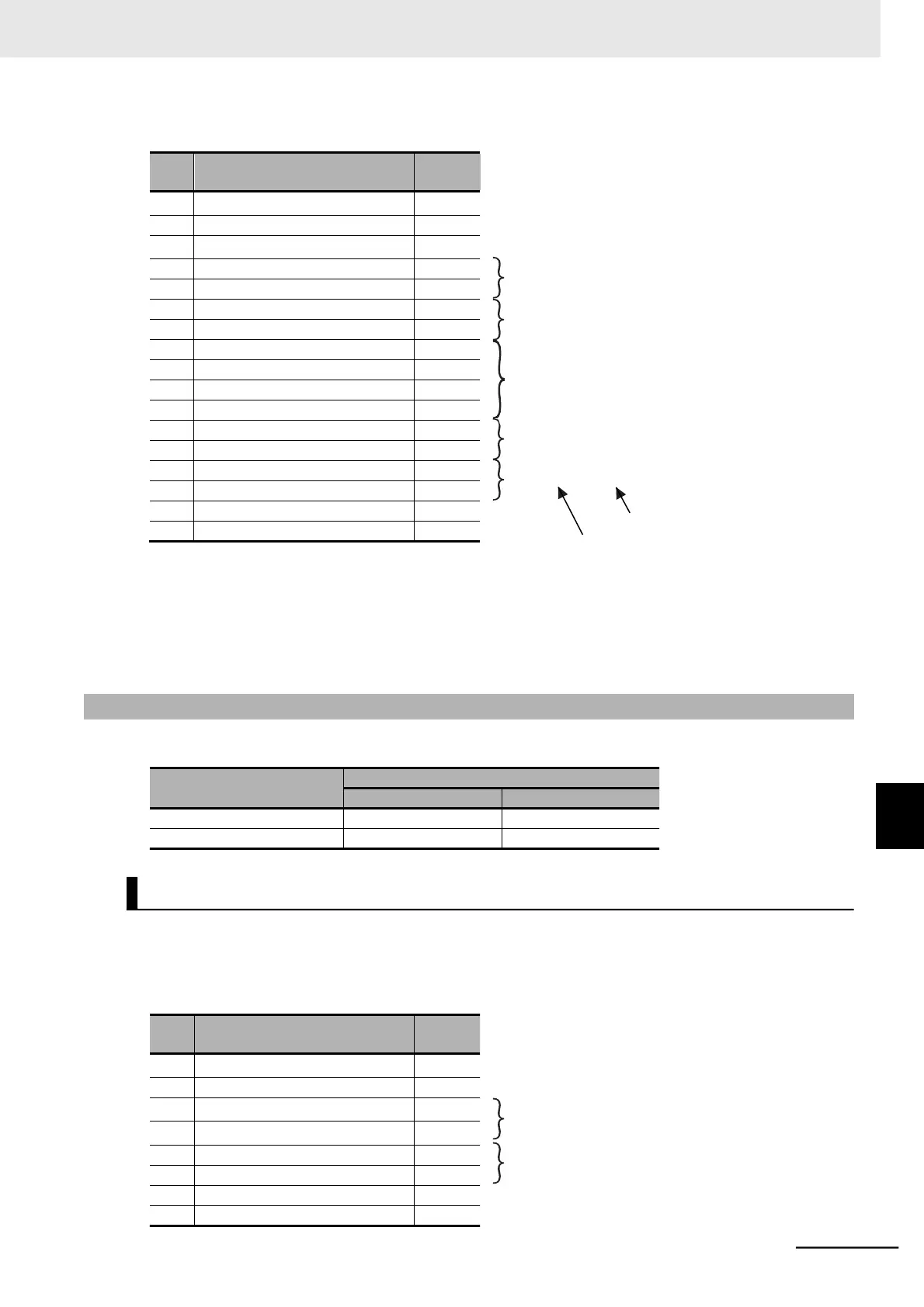
8-5-3 Write to Coil [05 hex]
Writes the ON/OFF status to a single coil. The coil status changes as shown in the table below.
You need to set the 1st RUN Command Selection (A002) to03 (Modbus communication).
The coil number for the RUN command is 0001.
⚫
Query
(Coil address) = (Coil number) − 1
OFF to ON: FF00 hex
 Loading...


