Multi-function Compact Inverter 3G3MX2-EV2 User’s Manual (I666-E1)
7-8-18 Low Current Signal (LOC)
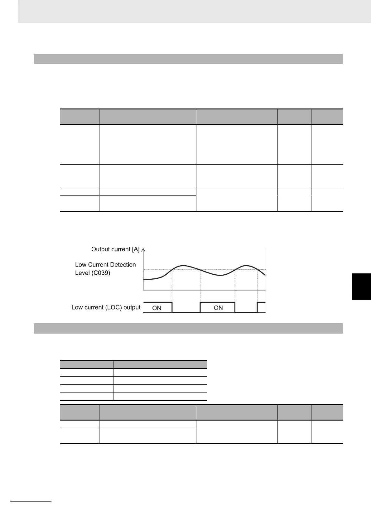
This signal will be output when the output current falls to or below the Low Current Detection Level
(C039).
In the Low Current Signal Output Selection (C038), select whether to have the inverter output this sig-
nal constantly during run or only during constant speed operation.
Low Current Signal Output Selection
00: Enabled during accelera-
tion/deceleration and
constant speed
01: Enabled during constant
speed
*1
Low Current Detection Level
0.00 to 2.00 Rated current
Set the output level of the low
current signal.
Multi-function Output 11/12 Selection
43: LOC (Low current signal)
Multi-function Relay Output (AL1, AL2)
Function Selection
*1. When the 1st/2nd Frequency Reference Selection (A001/A201) is set to 01 (Control circuit terminal block (An-
alog input)), the signal may not be judged as a constant speed depending on the sampling condition. In this
case, set C038 to 00 (Enabled during acceleration/deceleration and constant speed) or increase the value set
in the Analog Input Filter (A016).
7-8-19 Fatal Fault Signal (MJA)
If any of the following trips occurs, the inverter will output a separate signal besides the alarm signal
(05: AL).
Multi-function Output 11/12 Selection
53: MJA (Fatal fault signal)
Multi-function Relay Output (AL1, AL2)
Function Selection
7-8 Functions Related to Protection, Warning, and Various Output Signals
7-8-18 Low Current Signal (LOC)
 Loading...


