7-4 Inverter Control Settings
This section describes the carrier frequency function and the 1st/2nd control switching function, which
are related to the inverter control.
7-4-1 Carrier Frequency
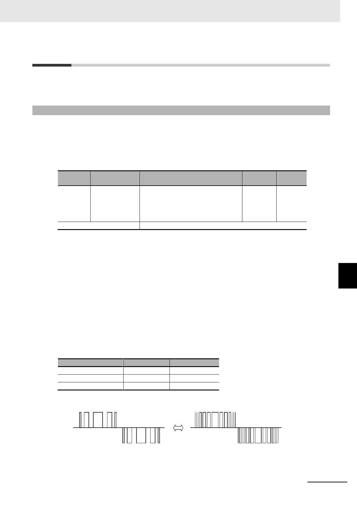
Use this function to change the carrier frequency output from the inverter in a PWM waveform.
Set a higher carrier frequency value to reduce the metallic noise generated by the motor. If the inverter
generates a large sound due to resonance with the mechanical system or motor, you can effectively
avoid the resonance by setting the carrier frequency out of the resonance frequency range.
However, this results in an increase in electrical noise or leakage current from the inverter.
•
b083 is applied to the carrier frequency for DC injection braking as well.
•
The DC injection braking power is restricted according to the selected carrier frequency. For details,
refer to 7-9-1 DC Injection Braking (DB) on page 7-93.
•
Derating of the output current may be required depending on the installation environment and the
Carrier Frequency (b083) setting. For derating of each inverter model, refer to A-1 Derating on page
A-2.
In the Electronic Thermal Level, set the output current value to be derated.
This setting, however, is unnecessary if the Electronic Thermal Level is already set to the derating
value or lower.
For details on the electronic thermal function, refer to 5-3-2 Electronic Thermal Function on page
5-15.
•
Be aware that adjusting the carrier frequency exceeding the allowable derating level for the output
current may cause damage or shortened life expectancy of the inverter.
•
The table below shows the carrier frequency setting and its influence.
 Loading...


