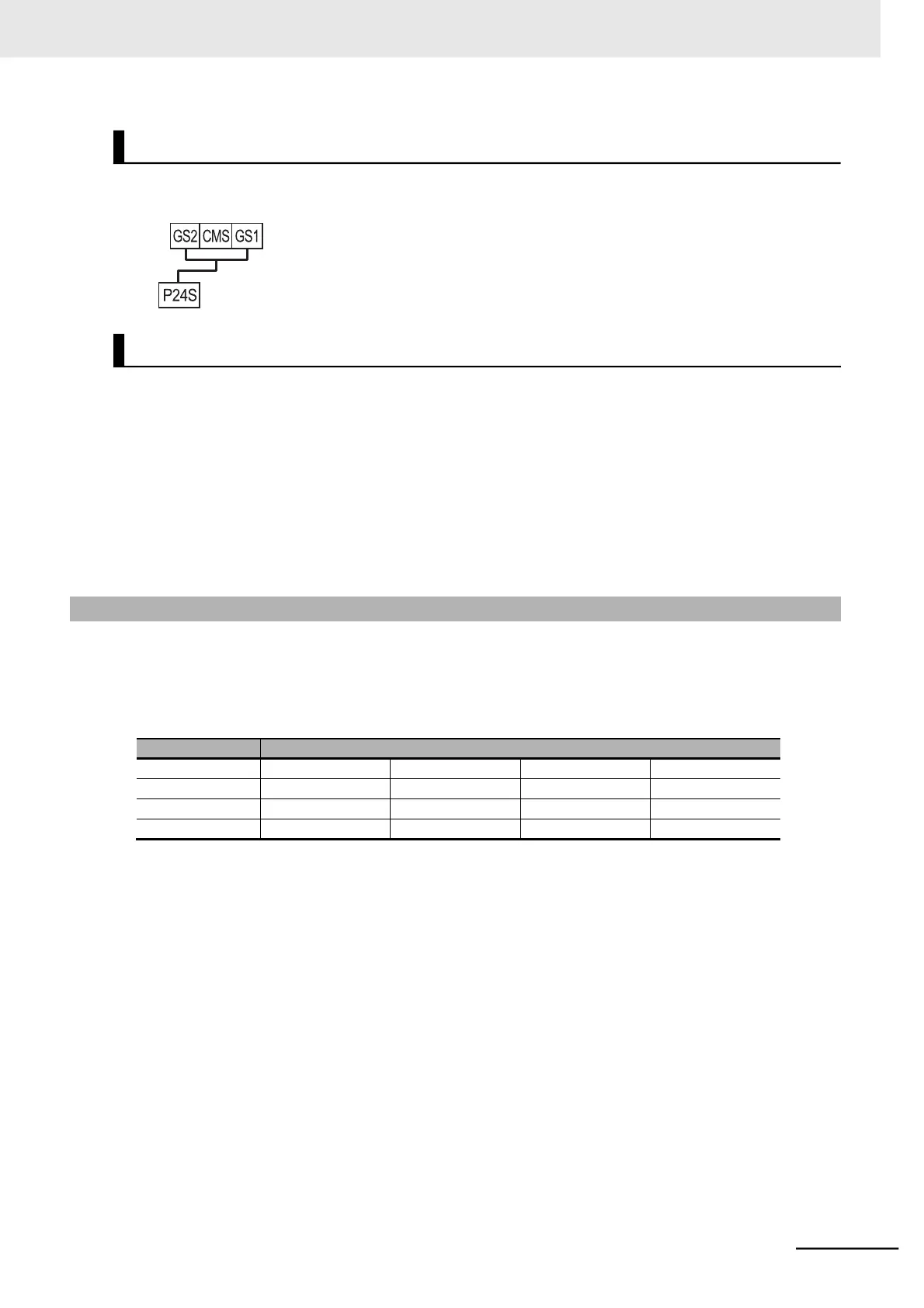
To disable the STO function, connect a short-circuit wire as shown in the figure below. This is the fac-
tory default wiring.
All power supplies connected to the control terminals of the 3G3MX2-EV2 Series Inverter must be
SELV or PELV compliant.
The signal lines for GS1 and GS2 must be physically separated or properly protected.
For all devices used for STO signal transmission, use products that comply with functional safety stan-
dards such as ISO13849-1 and IEC61508.
To achieve a system that complies with Cat 3/PLe and SIL3 as a whole, you must use the 3G3MX2-EV2
Series Inverter in combination with at least PLe- and SIL3-compliant devices.
The pulse width of test pulses input to GS1 and GS2 from external devices must be 500 µs or less.
7-10-4 Periodic Inspection
When the safety input function is activated, the inverter shuts off its output if the current does not flow in
either the terminal GS1 or GS2. Therefore, you must check the inverter periodically to ensure that there
is no defect in the GS1 and GS2 wirings. Be sure to perform periodical inspection at least once a year.
For the wiring information on the terminals GS1, GS2, and EDM, refer to the table below.
 Loading...


