Multi-function Compact Inverter 3G3MX2-EV2 User’s Manual (I666-E1)
Additional Information
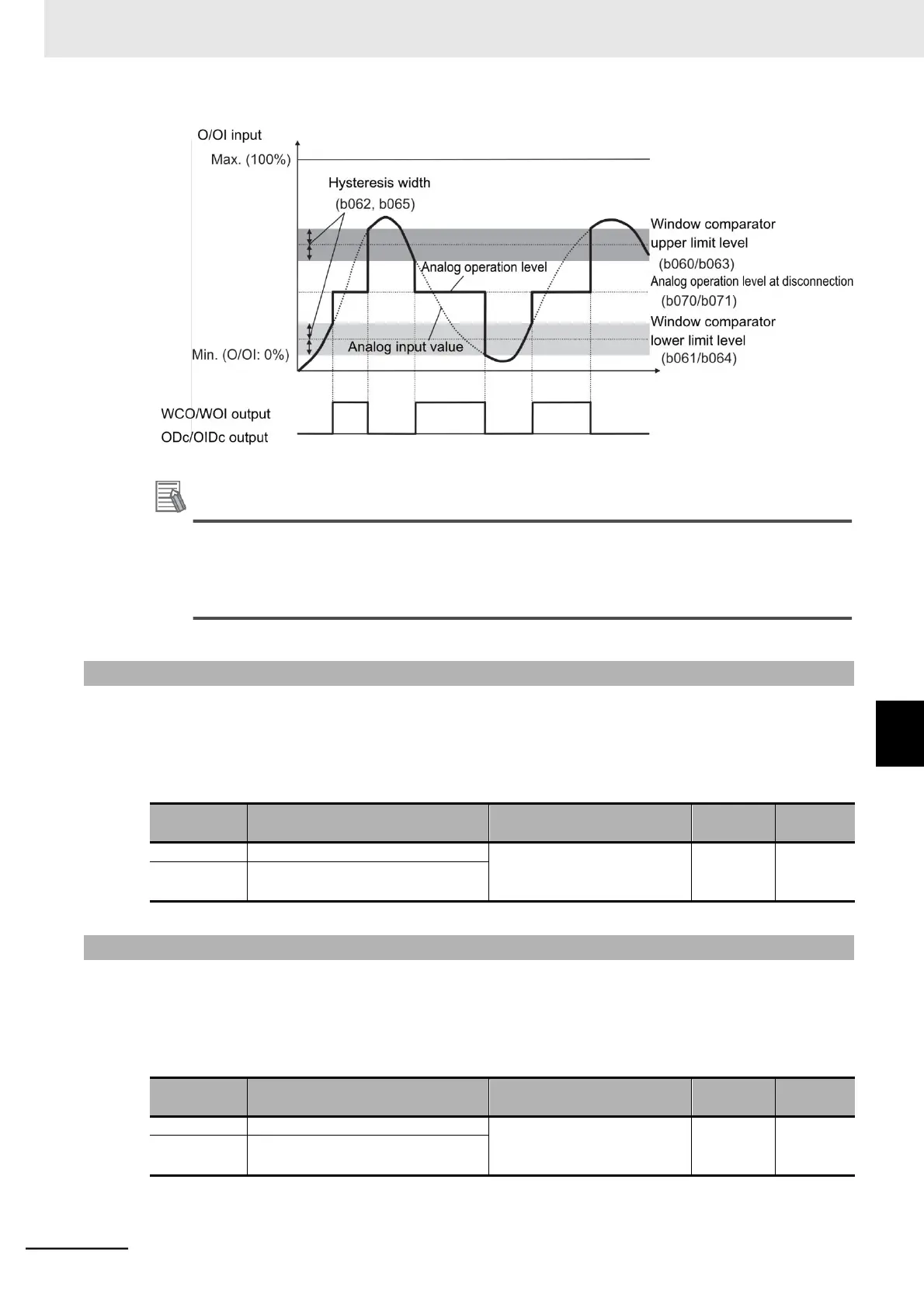
To use this function for disconnection detection, set the disconnection detection level in the
Window Comparator O/OI Upper Limit Level (b060/b063).
(In this case, the inverter uses the bandwidth over the upper limit value in normal operation
and, if the input falls below the upper limit value, the inverter detects a disconnection error.)
7-8-21 Frequency Reference Selection Status Signal (FREF)
This signal will be output when the RUN command is input via the Digital Operator (A001=02), or when
the forced operator function (31: OPE) is allocated to one of the multi-function output terminals and that
terminal is ON.
It is OFF when the RUN command is not input via the Digital Operator.
Multi-function Output 11/12 Selection
58: FREF (Frequency com-
mand source)
Multi-function Relay Output (AL1, AL2)
Function Selection
7-8-22 RUN Command Status Signal (REF)
This signal will be output when the RUN command is input via the Digital Operator (A001=02), or when
the forced operator function (31: OPE) is allocated to one of the multi-function output terminals and that
terminal is ON.
It is OFF when the RUN command is not input via the Digital Operator.
Multi-function Output 11/12 Selection
59: REF (RUN command
source)
Multi-function Relay Output (AL1, AL2)
Function Selection
7-8 Functions Related to Protection, Warning, and Various Output Signals
7-8-21 Frequency Reference Selection Status Signal
(FREF)
 Loading...


