7-3 Analog I/O Settings
This section describes the analog I/O signal settings for this inverter.
7-3-1 Analog Input (O, OI)
This inverter has two types of external analog input terminals.
Frequency reference (Analog voltage input) between terminals O and L : 0 to 10 V
This terminal also treats input via the variable resistor (volume) as voltage input to the
inverter.
Frequency reference (Analog current input) between terminals OI and L : 4 to 20 mA
For 0 to 20 mA, set A103 to 0%.
For analog input start/end settings, refer to 7-3-5 Analog Input Start/End Function Settings on page 7-25.
Note 1. By default, each analog input signal is adjusted to reach the maximum frequency at 9.8 V or 19.8 mA.
2. If an excessive current is applied to the terminal OI, an E26 (analog current input error) will occur.
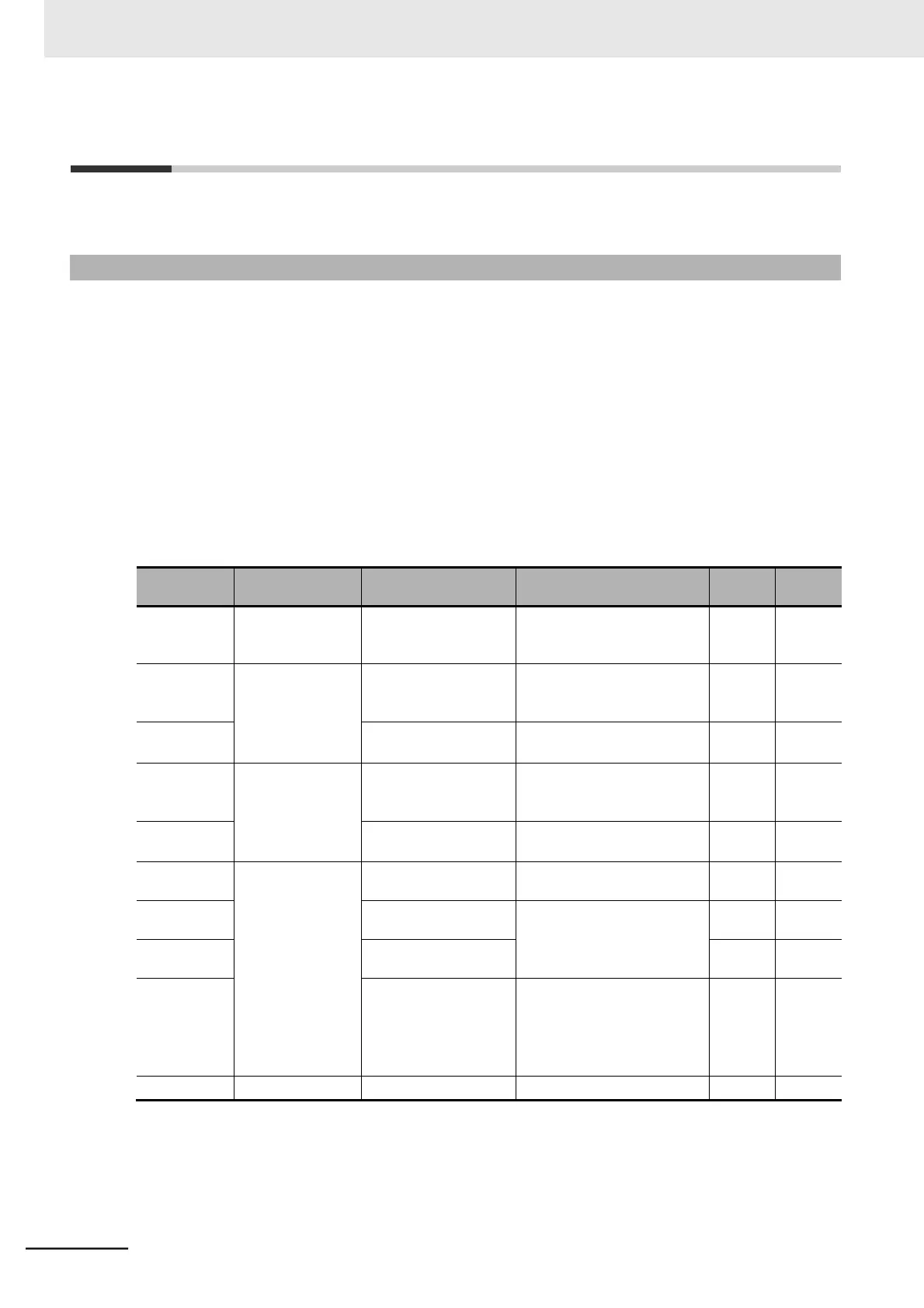
The table below shows analog-input related functions. Set each function according to your application.
 Loading...


