Multi-function Compact Inverter 3G3MX2-EV2 User’s Manual (I666-E1)
To install the terminal block cover, reverse the removal procedure.
Install the terminal block cover on the inverter from the top and press it until you here a click.
2-2-2 Terminal Blocks
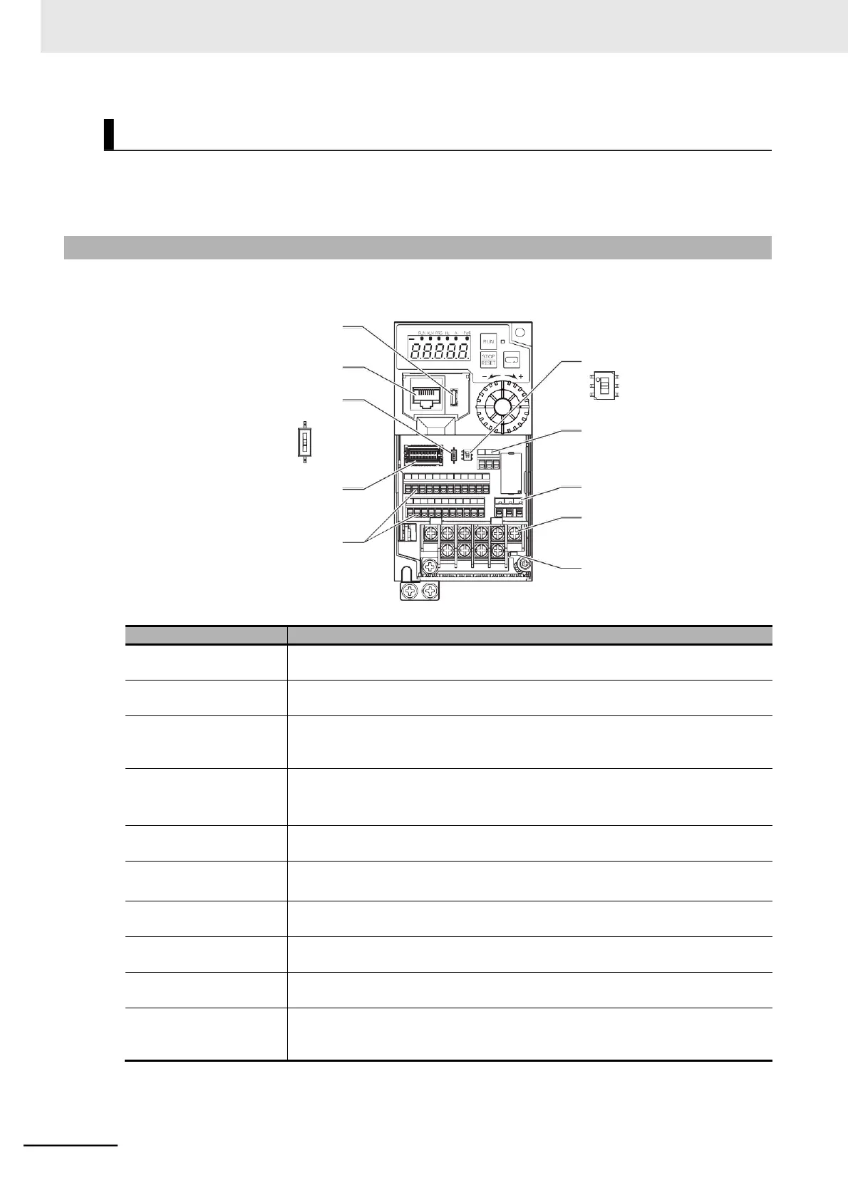
Removing the terminal block cover and each connector cover reveals terminal blocks, connectors, and
switches arranged as shown below.
USB Connector (Micro-B)
Operator Connector (RJ45)
Terminating Resistor Selector Switch
EDM Function Selector Switch
ON (EDM output)
OFF (Terminal 11 output)
(Factory default)
ON
OFF
(Factory default)
Connector for Option Unit
Control Circuit Terminal Block
Safety function
STO input terminal block
Relay Output Terminal Block
Main Circuit Terminal Block
Charge Indicator
Terminating resistor selec-
tor switch
The switch for switching ON/OFF the RS-485 terminal on the control circuit terminal
block. When ON, the terminal is connected to the built-in 120- terminating resistor.
Safety function STO input
terminal block
Dedicated terminals for safety input.
EDM function selector
switch
Turn this switch ON to use the EDM output of the safety function. Before you turn
ON/OFF this switch, be sure to turn off the power supply. For details, refer to 7-10
Safety Function on page 7-99.
The Micro-B type USB connector for connecting a computer.
Use this connector to connect the inverter to the Inverter/Servo support tool
CX-Drive.
Connector for Digital
Operator
The connector for connecting the Digital Operator.
Connector for Option Unit
The connector for connecting an option unit.
Use this connector to connect such as a communications option unit.
Control Circuit Terminal
Block
The terminal block for connecting various digital/analog I/O devices used for inverter
control.
Relay output terminal
block
The SPDT contact terminal block for relay output.
Main circuit terminal block
The terminal block for connecting the main power supply for the inverter, outputs to
the motor, Braking Resistor, etc.
Lights up even after power supply shutoff if the main circuit DC voltage (between the
terminal P/+2 and terminal N/−) is approximately 45 V or higher. Make sure the
charge indicator is not lit before wiring etc.
Note For the description of the data display and operation keys, refer to Section 3 Operation and Test Run.
Installing Terminal Block Cover
 Loading...


