5-8 Reset Method Settings
5-8-1 Reset
•
Use the reset function to reset the trip status of the inverter. This function is used also when the
inverter is running normally to shut off the inverter output.
To prevent the reset function from being activated when the Inverter is running normally, set the
Reset Selection (C102) to 02 (Enabled only during trip) or 03 (Reset only during trip).
•
If the reset signal is input to the inverter, calculated electronic thermal function data, calculated
regenerative braking usage rate data, multi-function pulse counter data, current position monitor
data, and internal counter data used for the protective function are cleared. To prevent these data
from being cleared, set the Reset Selection (C102) to 03 (Reset only during trip).
•
Setting the STOP Key Selection (b087) to 00 (Enabled) or 02 (Only RESET enabled) enables the
input of the reset signal via the STOP/RESET key on the Digital Operator.
•
To input the reset signal via the control circuit terminal block, set the Multi-function Input 1 to 7
Selection (C001 to C007) to 18 (RS: Reset).
•
The terminal RS (Reset) only supports NO (normally open contact) as the input method. The
Multi-function Input 1 to 7 Operation Selection (C011 to C017) cannot be set to 01 (NC: Normally
closed contact). Be sure to set the NO contact.
•
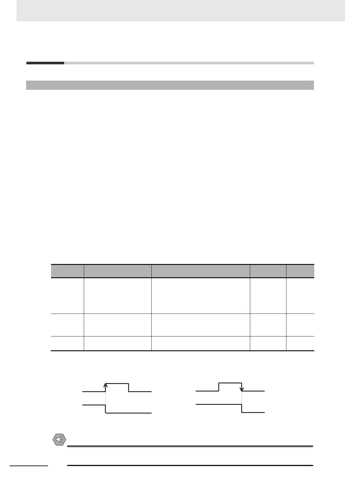
Setting the Reset Selection (C102) to 01 (Trip reset at power-off) enables the reset function to be
activated at the falling edge of the signal.
•
In the Reset Restart Selection (C103), select the restart method after reset is executed.
When the Reset Restart Selection (C103) is set to 00 (0-Hz restart), the inverter restarts from 0 Hz.
In addition, when the Reset Selection (C102) is set to 03 (Trip reset only), the inverter restarts from 0
Hz independently of the C103 setting.
 Loading...


