7-3-7 Terminal AM (Analog Output)
The terminal AM provides an analog output of 0 to 10 VDC.
The digital terminal AM on the control circuit terminal block enables the monitoring of the output fre-
quency and the output current.
The analog output may not stabilize immediately after the power is turned on or off.
Select the signal you want to output from the following table.
*1. 07 (LAD frequency) represents the frequency commanded by the inverter and is equivalent of the Output Fre-
quency Monitor (d001) value. 00 (Output frequency) represents a frequency value that takes into account the
aspects of vector control compensation (such as sensorless vector control) and even stabilization control.
When set to 00 (Output frequency), the parameter may produce an output that appears to be unstable at low
speeds, for example, when decelerating due to the overload limit function. In this case, set it to 07 (LAD fre-
quency) to obtain a stable output.
*2. Setting the Pulse Train Input EA Selection (P003) to 01 (Feedback pulse) causes the inverter to output the
frequency displayed in the Real Frequency Monitor (d008).
*3. This setting is enabled only when the 1st/2nd Control Method (A044/A244) is set to 03 (Sensorless vector con-
trol). When A044/A244 is not set to 03, the inverter does not produce output because it remains at 0 V.
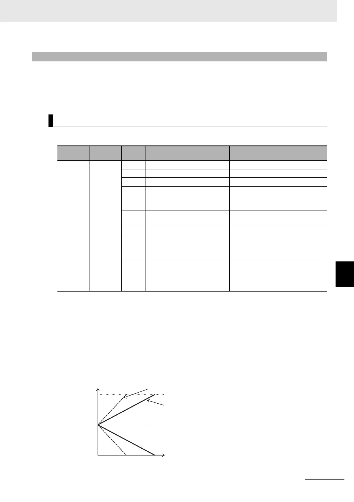
*4. The specifications of the output torque (signed) are as follows.
AM output [V]
10
5
AM Gain Setting (C106) = 200%
AM Gain Setting (C106) = 100%
AM Bias Setting (C109) = 50%
0
100
200
Torque [%]
 Loading...


