*1. When both the forward RUN command and the reverse RUN command are ON or OFF, the inverter does
not start its output.
*2. The inverter recognizes the rotation direction via RUN command input because it cannot recognize the ro-
tation direction by the single-phase pulse train.
However, if the RUN command is switched during operation, the inverter retains the rotation direction before
the switching until its output frequency causes a deceleration stop and then switches to the rotation direction
recognized via RUN command input.
6-5-2 Recommended Encoder and Its Wiring
For the pulse train input function of the 3G3MX2-EV2 Series Inverter, be sure to use a
complemen- tary-output type encoder.
In addition, for encoder cable connection, always use a shielded cable and connect it to the terminal L of
the inverter’s control circuit terminal block.
If an open-collector output encoder is used, the inverter may not recognize the rotation in the forward or
reverse direction. This is because, as the length of the encoder cable increases, its stray capacitance
becomes larger, which causes the inverter to falsely recognize the crosstalk signal from the encoder.
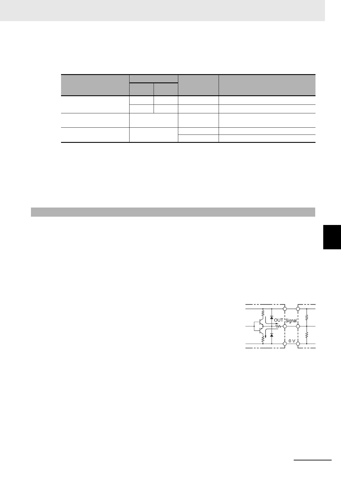
⚫
Complementary output
Complementary output is a method to output via two tran-
sistors.
The wiring is connected to the 0-V side when output is ON
and to the power-supply side when output is OFF.
This design does not allow the wiring to be left open (at high
impedance) as with the case of open-collector output
encoders.
Therefore, this provides a stable output from the encoder.
NPN
Transistor
PNP
Transistor
E6C3-CWZ5GH
Power
 Loading...


