*2. The management inverter sends the master switching command from Inverter No. 01 to 02 after data is sent
from Inverter 01 (master) to a slave (or slaves), with a wait time of “silent interval + Communication Wait Time
(C078).
*3. After receiving data from the master inverter, the management inverter sends the next master switching com-
mand with a wait time of “silent interval + Communication Wait Time (C078). If the management inverter can-
nnot receive the data sent from the master inverter within the Communication Error Timeout Time (C077), a
communication timeout occurs and the management inverter follows the operation set in the Operation Selec-
tion on Communication Error (C076).
*4. Be sure to enable the Communication Error Timeout Time setting (C077 = 0.01 to 99.99) on the management
inverter. When this setting is disabled (C077 = 0), the co-inverter communication will stop if the management
inverter cannot receive data from the master. In this case, cycle the power supply for the management
inverter, or reset the management inverter (by turning ON/OFF the terminal RS).
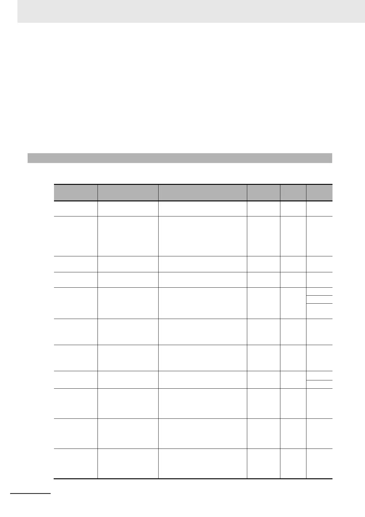
8-8-1 Co-inverter Communication Parameters
The parameters required to establish co-inverter communication are shown in the table below.
 Loading...


