Allocate the Multi-function Output 11/12 Selection (C021/C022) or Multi-function Relay Output (AL1,
AL2) Function Selection (C026) to 12 (ONT: Power ON time over).
Set the RUN Time/Power ON Time Detection Level (b034).
7-8-11 Logic Operation Output Signal (LOG1 to LOG3)
Use these signals to have the inverter internally perform logical operations with output signals. Set the
Multi-function Output 11/12 Selection (C021/C022), or Multi-function Relay Output (AL1, AL2)
Function Selection (C026), to 33 (LOG1: Logic operation output 1), 34 (LOG2: Logic operation output
2), or 35 (LOG3: Logic operation output 3). The logic output signal selection parameters cannot be
set to 255 (no: No allocation), 63 (OPO: Option), or 33 to 35 (LOG1 to LOG3: Logic operation output
1 to 3).
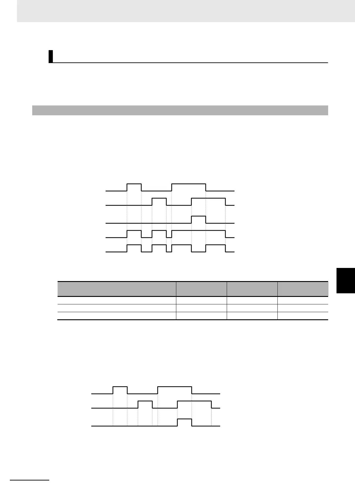
Three operators, AND, OR, and XOR, are available.
Logic output sig-
nal selection 1
Logic output sig-
nal selection 2
LOGx (AND)
LOGx (OR)
LOGx (XOR)
Each logic operation output signal requires different parameter settings.
Set the necessary parameters according to the table below.
(Example) To output the result of the AND operation between RUN (00: Signal during RUN) and FA2
(01: Set frequency exceeded signal) to the multi-function output terminal 12 as a logic oper-
ation output 1 (LOG1) terminal
Multi-function Output 12 Selection (C022) : 33 (LOG1)
Logic Output Signal 1 Selection 1 (C142) : 00 (RUN)
Logic Output Signal 1 Selection 2 (C143) : 02 (FA2)
Logic Output Signal 1 Operator Selection (C144) : 00 (AND)
RUN
FA2
LOG1
 Loading...


