11 Maintenance and Inspection
Multi-function Compact Inverter 3G3MX2-EV2 User’s Manual (I666-E1)
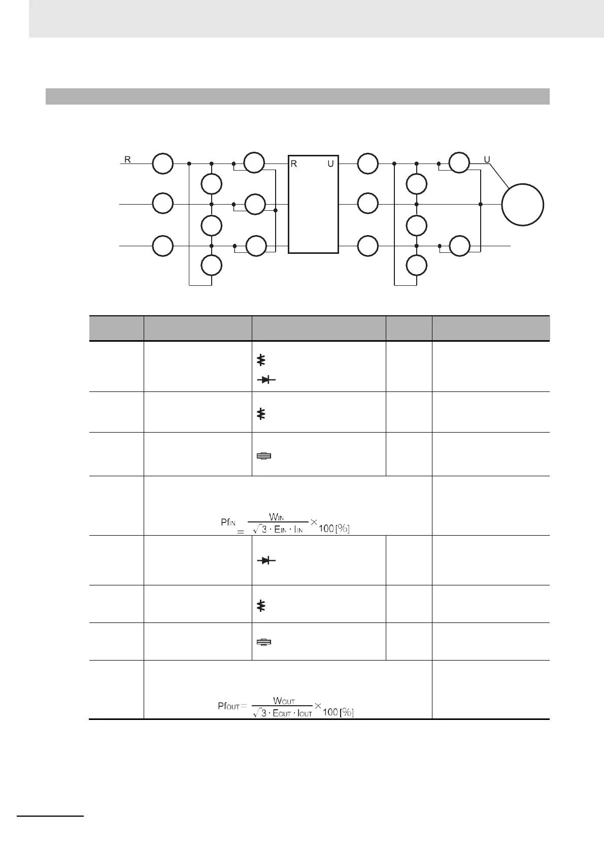
11-1-8 I/O Voltage/Current/Electric Power Measurement Method
Measuring instruments commonly used for input/output voltage, current, or electric power measure-
ment are shown below.
Power
supply
Measurement
value reference
Between R/L1 and S/L2 (E
R
)
Between S/L2 and T/L3 (E
R
)
Between T/L3
and
R/L1
(E
R
)
Moving-iron voltmeter
or rectifier type voltme-
ter
200-V class:
200 to 240 V,
50/60
Hz
400-V class:
380 to 480 V,
50/60
Hz
Current in R/L1, S/L2
T/L3: (IR), (IS), (IT)
When input current is not
balanced:
IIN = (IR + IS + IT) / 3
Between R/L1 and S/L2 (W
I1
)
Between
S/L2
and
T/L3
(W
I2
)
Between
T/L3
and
R/L1
(W
I3
)
Electrodynamic watt-
meter
Three-wattmeter method
(WI1) + (WI2) + (WI3)
Calculate this from the measured values of power supply voltage EIN,
power supply current IIN, and input electric power WIN.
Between U/T1 and V/T2 (E
U
)
Between V/T2 and W/T3 (E
V
)
Between
W/T3
and
U/T1
(E
W
)
Refer to the figure on
the next page. (Or recti-
fier type voltmeter)
Effective
value of
fundamental
wave
Current (IU), (IV), (IW) of
U/T1, V/T2, W/T3
Between U/T1 and V/T2 (W
O1
)
Between V/T2 and W/T3 (W
O2
)
Electrodynamic watt-
meter
Two-wattmeter method (or
three-wattmeter method)
(WO1) + (WO2)
Output
power
factor
PfOUT
Calculate this from the measured values of output voltage EOUT, out-
put current IOUT, and output electric power WOUT.
Note 1. For the output voltage, use a measuring instrument that shows effective values of fundamental wave.
For the current and the electric power, use a measuring instrument that shows all effective values.
2. The output waveform of the inverter has a margin of error, especially at low frequencies, because it was
generated under PWM control. Note that many general-purpose testers may not be usable due to noise.
 Loading...


