Generally, the forward rotation is defined as the direction in which the motor wired in direct UVW phase
sequence to the inverter rotates counterclockwise when viewed from the shaft. This is corresponding to
European motor convention. In other parts of the world, motor convention is clockwise.
Forward
7-1-4 PID Feedback Value Monitor [d004]
Use this function to monitor the PID feedback value when the PID Selection (A071) is set to 01
(Enabled) or 02 (Reverse output enabled).
The monitor value is displayed in units of percentage as 100% of the 1st/2nd Maximum Frequency
(A004/A204) and can be converted by setting the PID Scale (A075) as follows.
d004 = Feedback value [%] PID Scale (A075)
*1. The digit shift display mode can be used.
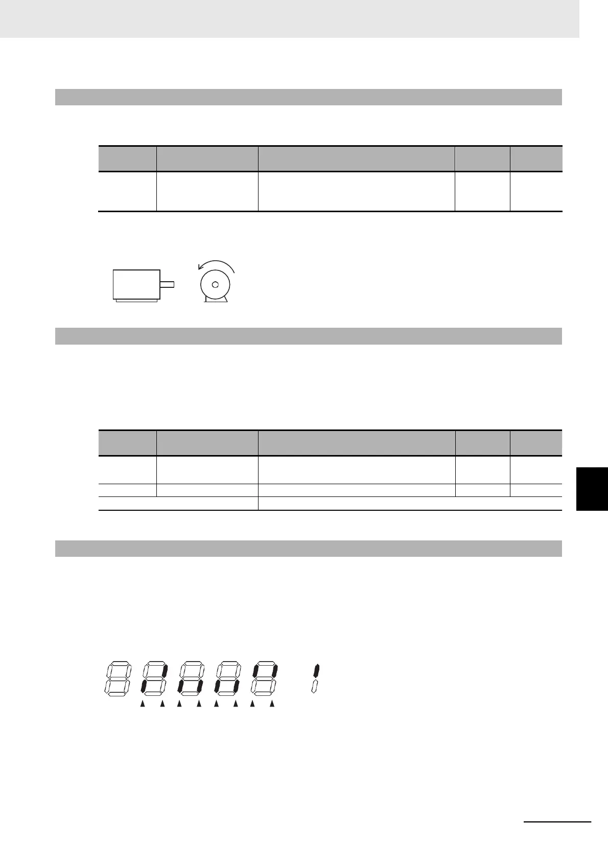
7-1-5 Multi-function Input Monitor [d005]
Use this function to display the input status of each multi-function input terminal, based on whether the
corresponding 7-segment LED is lit or not lit.
The terminal for which the built-in CPU detected the input is indicated as ON. Note that this is indepen-
dent of the NO/NC contact setting for each multi-function input terminal.
(Example) Multi-function input terminals 7, 2, and 1 : ON
Multi-function input terminals 6, 5, 4, and 3 : OFF
Display
EA
7 6
5
4
3 2 1
(OFF)
(ON) (OFF)(OFF)(OFF)(OFF)(ON)
(ON)
ON
OFF
: Lit
: Not lit
•
When the input terminal response time function is enabled, the inverter cannot display the input sta-
tus immediately. (Refer to 5-9-3 Input Terminal Response Time on page 5-47.)
•
The terminal 5 remains OFF and cannot be monitored when Multi-function Input 5 Selection
(C005) is allocated to 19 (TH: PTC thermistor thermal protection).
 Loading...


