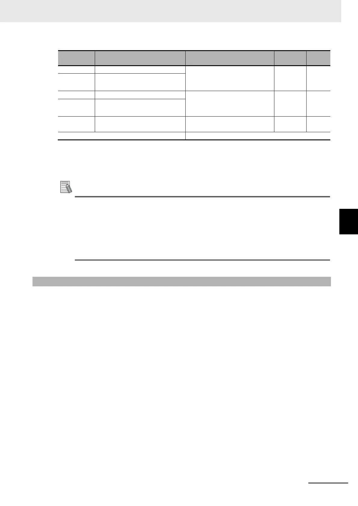
*1. To enable the switching to the 2nd Acceleration/Deceleration Time 1, set one of the Multi-function Input 1 to 7
Selection (C001 to C007) to 08 (SET) and turn ON that terminal.
*2. The digit shift display mode can be used.
*3. In high-frequency mode.
Additional Information
If a short deceleration time is set, the amount of regeneration fed back during deceleration
becomes large. If the amount of regeneration exceeds the amount allowable for the inverter,
the deceleration time will be extended according to the Overvoltage Suppression Function
Selection During Deceleration (b130) setting, or an overvoltage protection (E07.) is detected.
In such a case, use the regenerative braking function to shorten the deceleration time below
the set value.
For the regenerative braking function, refer to 5-12-2 Regenerative Braking Function on page
5-64.
5-6-2 Acceleration/Deceleration Pattern
•
Use this function to set the acceleration/deceleration pattern for each system.
•
Select the acceleration/deceleration pattern in the Acceleration Pattern Selection (A097) and Decel-
eration Pattern Selection (A098).
•
The acceleration pattern and the deceleration pattern can be set independently.
•
These acceleration/deceleration pattern settings are enabled also for frequency reference input via
analog input terminals.
•
When the acceleration/deceleration pattern is set to EL-S-shape curve, do not change the frequency
reference during acceleration/deceleration. Even if the frequency reference is changed during accel-
eration/deceleration, the inverter operates with the EL-S-shape curve before the change, however
the frequency reaches the changed frequency reference.
•
In the high-frequency mode, the Acceleration Pattern Selection (A097) and Deceleration Pattern
Selection (A098) are fixed to 00 (Line) and thus A097 and A098 are not displayed.
 Loading...


