1.5 Connectors and their Pinouts
All of VersaSync's connectors are provided at the front panel of the unit, below the Status
LEDs. The Advanced Military Connectors are keyed for foolproof connectivity and offer a
push-pull locking mechanism.
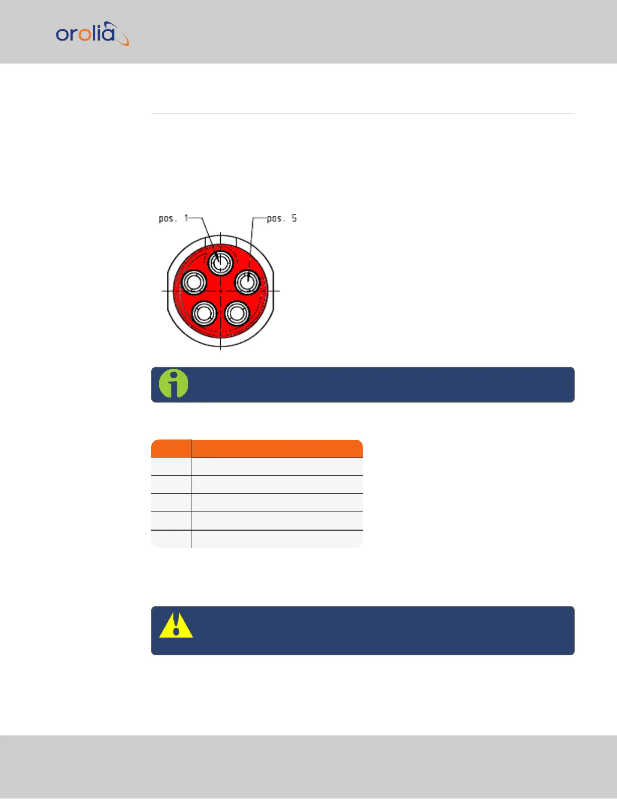
1.5.1 Power Connector
Note: View in mating direction from front.
Table 1-5:
Power connector pinout
Pin Signal
1 V
Main
(10 to 32V)
2 -not used-
3 V
Standby
(10 to 32 V)
4 GND (to Standby)
5 GND (to Main)
This product is designed to handle a maximum voltage of up to 32 V
DC
. Power supplies
with higher voltage or transient/ cranking power will require a power conditioner or surge
blocker.
Caution: Reversed polarity can blow an internal fuse that protects the
product from damage. Use care when building power cables.
1.5 Connectors and their Pinouts
CHAPTER 1 • VersaSync User Manual Rev. 7.0
9
 Loading...