4.32
9929422 R02 - 2017-2019 ACE 900 Service Manual
© Copyright Polaris Industries Inc.
CRANKSHAFT POSITION SENSOR (CPS)
CPS OVERVIEW
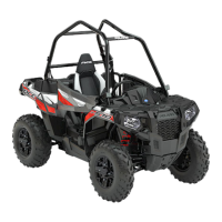
Mounted on top of the stator cover, the crankshaft
position sensor
q
is essential to engine operation,
constantly monitoring the rotational speed (RPM) and
position of the crankshaft.
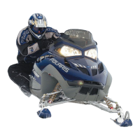
A ferromagnetic 35-tooth encoder ring
w
with a missing
tooth is built onto the flywheel. The inductive speed
sensor is mounted 1.0 ± 0.26 mm (0.059 ± 0.010″) away
from the encoder ring. During rotation, an AC pulse is
created within the sensor for each passing tooth. The
ECU calculates engine speed from the time interval
between the consecutive pulses.
The encoder ring missing tooth creates an “interrupt”
input signal, corresponding to specific crankshaft
position. This signal serves as a reference for the control
of ignition timing by the ECU. Synchronization of the
CPS and crankshaft position takes place during the first
two revolutions each time the engine is started. This
sensor must be properly connected at all times. If the
sensor fails or becomes disconnected for any reason, the
engine will stop running.
CPS TEST
NOTICE
The CPS is a sealed, non-serviceable assembly. If fault
code diagnosis indicates a problem with this sensor
circuit, test as follows:
RESISTANCE TEST
1. Access the CPS connector.
2. Disconnect CPS from the main harness connector.
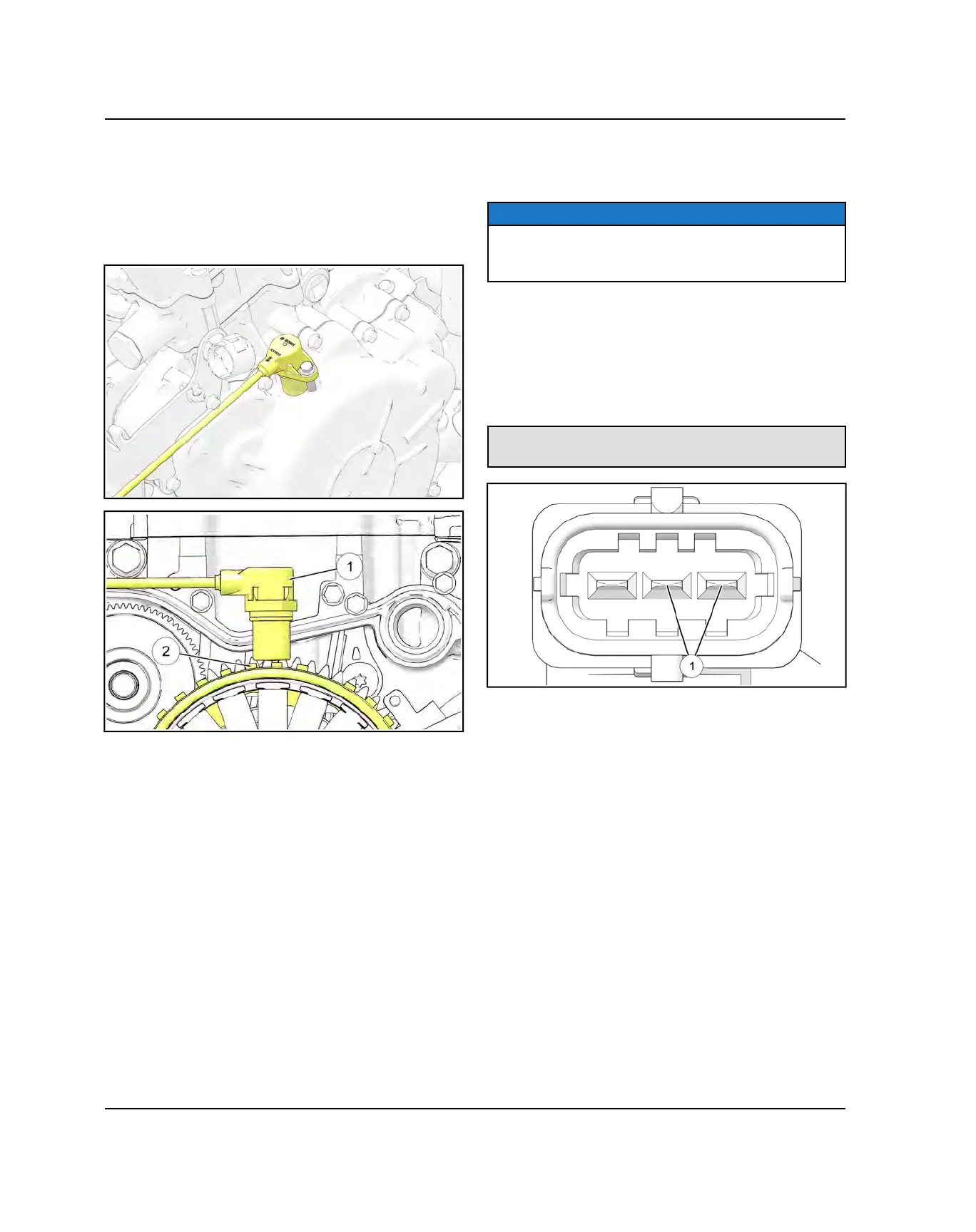
3. Measure the resistance between the CPS terminals
shown below
q
using an ohmmeter. Verify the
resistance at room temperature is within specification.
CPS Resistance Specification:
1000 Ω ± 10%
4. If the resistance is incorrect, follow the “CPS
Replacement” procedure.
5. If the resistance is correct, thoroughly inspect the
relevant wiring connections and chassis harness. An
electrical component , connection, or harness issue
may persist.
6. If all electrical connections have been verified and
problems persist, proceed to the next test.
7. Disconnect the ECU connector. Check continuity from
one wire at the CPS connector to the other end of the
circuit at the ECU connector. It should have less than
one ohm of resistance. If more than one ohm, locate
the cause of high resistance and recheck.
8. If under one ohm on both wires, leave one meter lead
on one CPS circuit wires with both connectors still
disconnected. Place the other lead on the battery
negative terminal. Check both wires in this matter.
They should both read OL, indicating no shorts to
ground.
FUEL SYSTEM

 Loading...