11
9929422 R02 - 2017-2019 ACE 900 Service Manual
© Copyright Polaris Industries Inc.
11.61
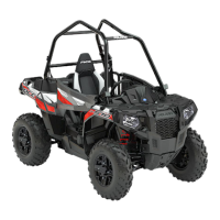
TERMINAL BLOCK
TERMINAL BLOCK OVERVIEW
A terminal block
q
is located under the removable front
storage compartment.
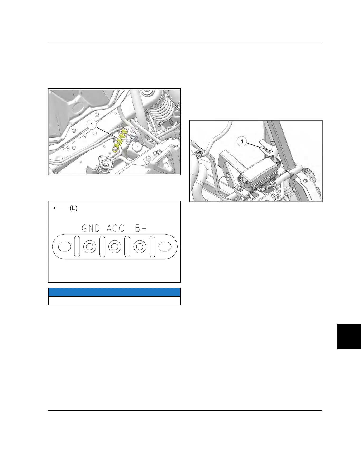
Connections made at the terminal block are: GND
“Ground” (Black and Brown), ACC “Accessory” (OG/
WHT), and B+ “Battery” (RED).
NOTICE
L = Left Side of Vehicle
The OG/WHT accessory power lug is protected by the
20A ACC Fuse and supplies power to the 12V dash
receptacle and rear accessory connector. The RED B +
power lug is connected to battery (+) via the starter motor
solenoid.
Use the terminal block when connecting accessories
such as light bars or when installing a winch.
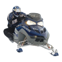
DIODES
BRAKE SWITCH DIODE
Because the brake pedal must be pushed to enable the
starter motor relay to activate, a diode is placed in the
OR brake switch circuit to prevent voltage back-feeding
through the brake lights when the brake pedal is not
pushed.
The diode is located in the main wire harness loom
q
next to the fuse / relay box.
ELECTRICAL

 Loading...