8.26
9929422 R02 - 2017-2019 ACE 900 Service Manual
© Copyright Polaris Industries Inc.
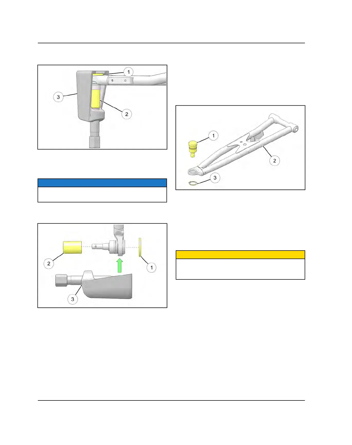
2. Using PU-50506, install spacer
q
over the top of the
ball joint face.
3. Place Removal Adaptor
w
over the ball joint shaft.
4. Install the Press Asm.
e
onto the A-arm to engage
the ball joint Removal Adapter.
NOTE
Be sure the Press Asm. opening is only contacting the
Spacer
q
and not the ball joint face.
5. Tighten the Press Asm. screw and fully remove the
ball joint from the A-arm.
BALL JOINT INSTALLATION
Upper Ball Joint Removal
1. By hand, install the NEW ball joint into the A-arm.
2. Using a press, carefully drive in the new ball joint into
the A-arm.
3. After the new ball joint
q
is fully installed into the A-
arm
w
, install a new retaining ring
e
.
4. Repeat the ball joint service procedure for any
additional A-arm ball joint replacements.
5. Insert upper / lower A-arm ball joint end into the
bearing carrier. Install new pinch bolt and nut on
upper ball joint or new cotter pin and nut on lower ball
joint. Torque to specification.
6. If needed, install new brake caliper mounting bolts
and torque to specification.
CAUTION
New bolts have a pre-applied locking agent which is
destroyed upon removal. Always use new brake caliper
mounting bolts upon assembly.
STEERING / SUSPENSION

 Loading...