7
9929422 R02 - 2017-2019 ACE 900 Service Manual
© Copyright Polaris Industries Inc.
7.37
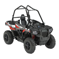
12. Carefully install the LH output hub assembly
o
into
the cover plate. Take care not to damage the new
cover plate seal while installing the output hub.
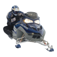
13. Install the output cover assembly
a
onto the
gearcase housing. Install the seven cover plate
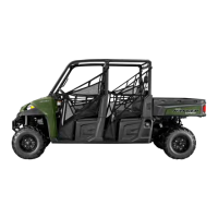
screws
s
and torque to specification.
TORQUE
Cover Plate Screws:
9 ft-lbs (12 Nm)
FRONT GEARCASE INSTALLATION
1. Reinstall front gearcase into vehicle from the right
side.
2. Install a new compression ring on left drive shaft.
Apply anti-seize compound to the splines. Insert drive
shaft into gearcase. Verify the shaft “clicks” into place.
3. Install the front gearcase frame fasteners. Torque
bolts to specification.
TORQUE
Gearcase Mounting Bolt:
30 ft-lbs (40 Nm)
4. Slide the prop shaft forward and align the hole in the
yoke with the hole in the gearcase input shaft. Apply
anti-seize to the input shaft splines.
5. Install prop shaft. Align holes, and then drive new
spring pin into hole until flush with surface of yoke.
6. Reconnect the front gearcase wire harness
connector. Attach the vent hose to the gearcase
fitting.
7. Install upper and main floor board panels. Reinstall
seat.
8. Install new compression ring on the right drive shaft.
Apply anti-seize compound to splines. Align splines of
drive shaft with front gearcase and install by lightly
tapping on drive shaft with soft-faced hammer.
9. Install drive shaft axle through the backside of the
bearing carrier.
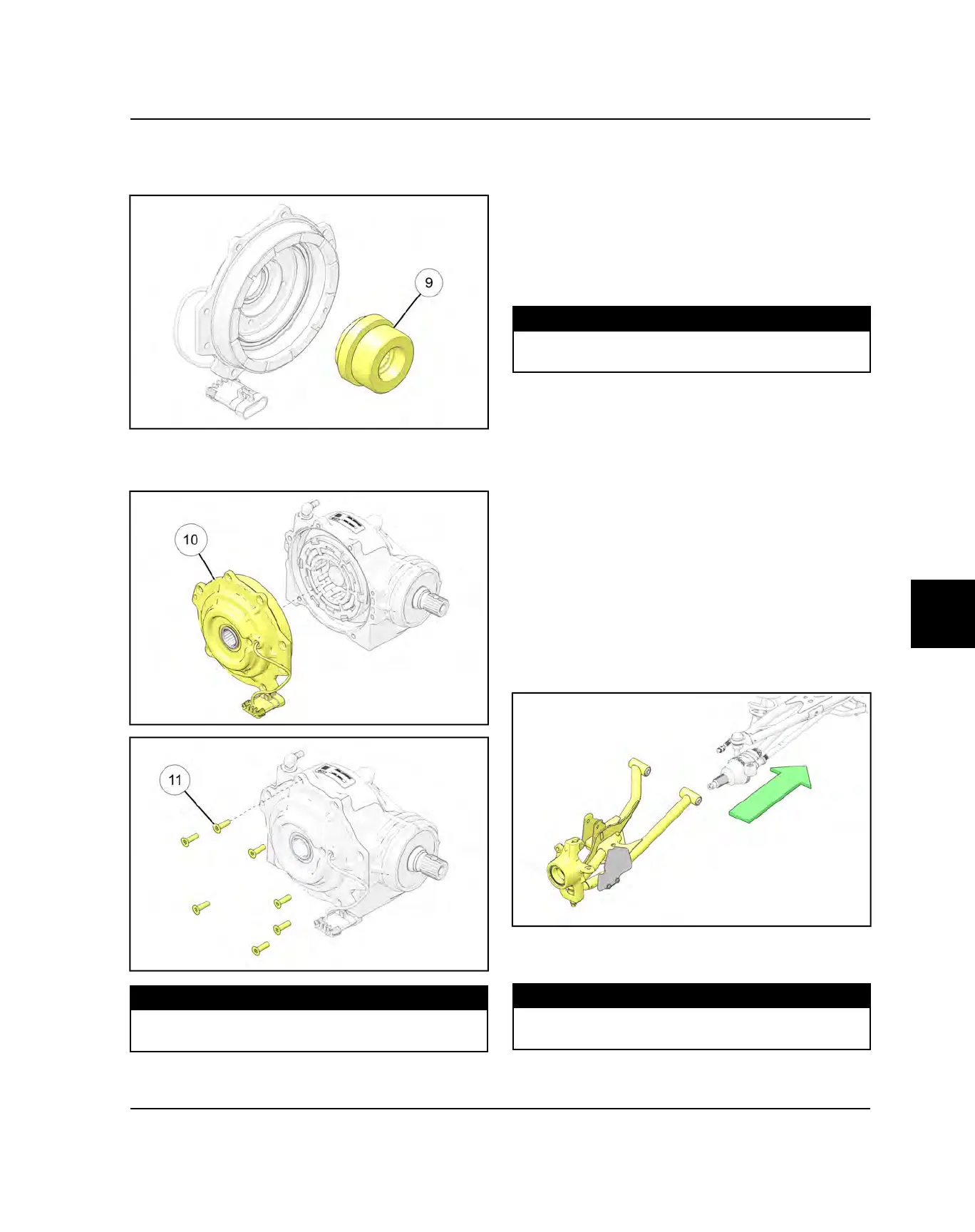
10.Install lower A-arm assembly onto vehicle frame.
Torque new bolts to specification.
TORQUE
Lower Control Arm Fasteners:
42 ft-lbs (57 Nm)
FINAL DRIVE

 Loading...