11
9929422 R02 - 2017-2019 ACE 900 Service Manual
© Copyright Polaris Industries Inc.
11.59
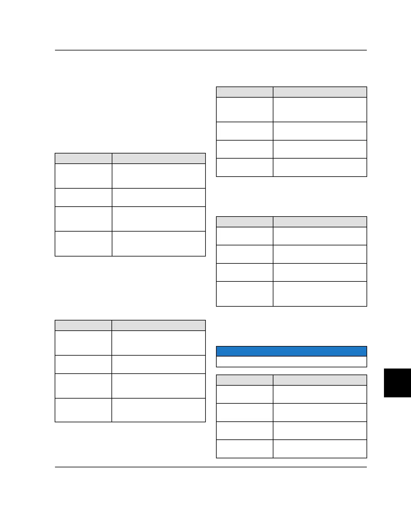
RELAY OPERATION
Located in the fuse box behind the engine compartment
access panel, the relays assist with component operation
like the cooling fan, fuel pump and EFI system, and drive
system.
CHASSIS RELAY provides power to the following
systems:
• Lights (Headlights / Taillights)
• Drive (AWD)
• Accessory (12V Receptacles / Accessory Options)
COLOR FUNCTION
Red
PIN 4 (Relay 30) - 30 Amp fuse
protected 12 Vdc constant
battery voltage.
Brown / White
PIN 8 (Relay 86) - Relay coil
ground.
Orange
PIN 3 (Relay 85) - 12 Vdc power
input from key switch to enable
relay.
White
PIN 7 (Relay 87) - Provides 12
Vdc power for lights, drive and
accessory circuits.
EFI RELAY provides power to the following systems:
• Fuel Injectors
• Ignition Coil
• Fan Relay
• Fuel Pump Relay
COLOR FUNCTION
Red / White
PIN 1 (Relay 85) - 20 Amp fuse
protected 12 Vdc constant
battery voltage.
Dark Green /
Yellow
PIN 6 (Relay 86) - ECU ground
input to enable relay.
Red / White
PIN 2 (Relay 30) - 20 Amp fuse
protected 12 Vdc constant
battery voltage.
Red / Dark Blue
PIN 5 (Relay 87) - Provides 12
Vdc power for EFI system
circuits.
FAN RELAY provides power to the following system:
• Fan Motor
COLOR FUNCTION
Red
PIN 10 (Relay 30) - 20 Amp
circuit breaker protected 12 Vdc
constant battery power.
Orange / White
PIN 14 (Relay 86) - ECU ground
input to enable relay.
Red / Dark Blue
PIN 9 (Relay 85) - 12 Vdc
switched power from EFI relay.
Orange / Black
PIN 13 (Relay 89) - Provides 12
Vdc power for fan operation.
FUEL PUMP RELAY provides power to the following
system:
• Fuel Pump
COLOR FUNCTION
Red / Green
PIN 18 (Relay 30) - 10 Amp fuse
protected 12 Vdc battery voltage.
Dark Green /
Yellow
PIN 22 (Relay 86) - ECU ground
input to enable relay.
Red / Dark Blue
PIN 17 (Relay 85) - 12 Vdc
switched power from EFI relay.
Red / Blue
PIN 21 (Relay 87) - Provides 12
Vdc power for fuel pump
operation.
ELECTRONIC POWER STEERING (EPS) RELAY -
OPTIONAL provides power to the following system:
• Electronic Power Steering Unit
NOTE
Only vehicles equipped with EPS will use this relay.
COLOR FUNCTION
Orange
PIN 33 (Relay 85) - Key switched
12 Vdc battery voltage.
Brown
PIN 38 (Relay 86) - Vehicle
ground.
Red
PIN 34 (Relay 30) - 30 Amp fuse-
protected 12 Vdc battery voltage.
Orange
Pin 37 (Relay 87) - 12 Vdc
battery voltage to EPS controller.
ELECTRICAL

 Loading...