11
9929422 R02 - 2017-2019 ACE 900 Service Manual
© Copyright Polaris Industries Inc.
11.29
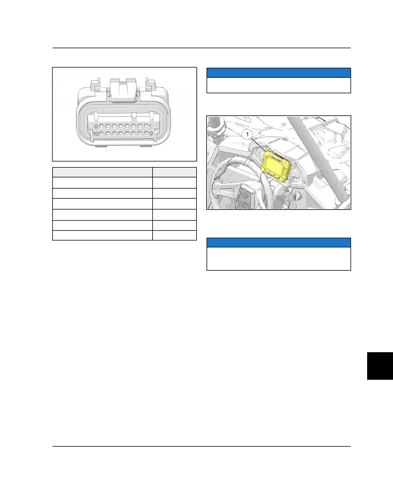
INSTRUMENT CLUSTER PINOUTS
FUNCTION
PIN
CAN High
1
CAN Low
2
Constant Power (Vdc) 3
Switched Power (Vdc)
4
Ground
5
Fuel Level Sensor
11
INSTRUMENT CLUSTER REMOVAL
NOTICE
Do not allow alcohol or petroleum products to come in
contact with the instrument cluster lens.
1. Disconnect the wire harness connector from the back
side of the instrument cluster.
2. Push the instrument cluster out from the back side of
the dash while securely holding the dash and rubber
mount.
NOTICE
Do not remove the rubber mount from the dash panel.
Only remove the rubber mount if necessary. The bezel
is a snap-on assembly and is a serviceable part.
INSTRUMENT CLUSTER INSTALLATION
1. Spray a soap and water mixture onto the outer
surface area of the instrument cluster. This will help
the instrument cluster slide into the rubber mount
more easily.
2. Be sure the rubber mount inside the dash is fully
installed and that the indexing key on the rubber
mount is lined up with the keyway in the dash.
3. Hold the dash securely and insert the instrument
cluster into the dash. Apply pressure on the bezel
while pressing down on the instrument cluster.
ELECTRICAL

 Loading...