5.20
9929422 R02 - 2017-2019 ACE 900 Service Manual
© Copyright Polaris Industries Inc.
34.Remove nut from puller rod. Take installation tool and
clutch cover off rod.
DRIVE CLUTCH ASSEMBLY
CAUTION
Do not apply oil or grease to the bushings.
Reassemble the drive clutch in the following sequence.
Be sure marks that were made during disassembly are
aligned during each phase of assembly.
1. Install the shift weights, bolts and nuts onto the
moveable sheave. Torque shift weight bolts to
specification.
TORQUE
Shift Weight Fasteners:
20 in-lb (2 Nm)
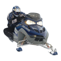
2. Install the non-braking needle bearing
q
, the two
washers
w
and the spacer
r
onto the stationary
sheave
e
.
3. Install moveable sheave onto stationary sheave shaft.
Be sure the moveable sheave slides freely on the
spacer.
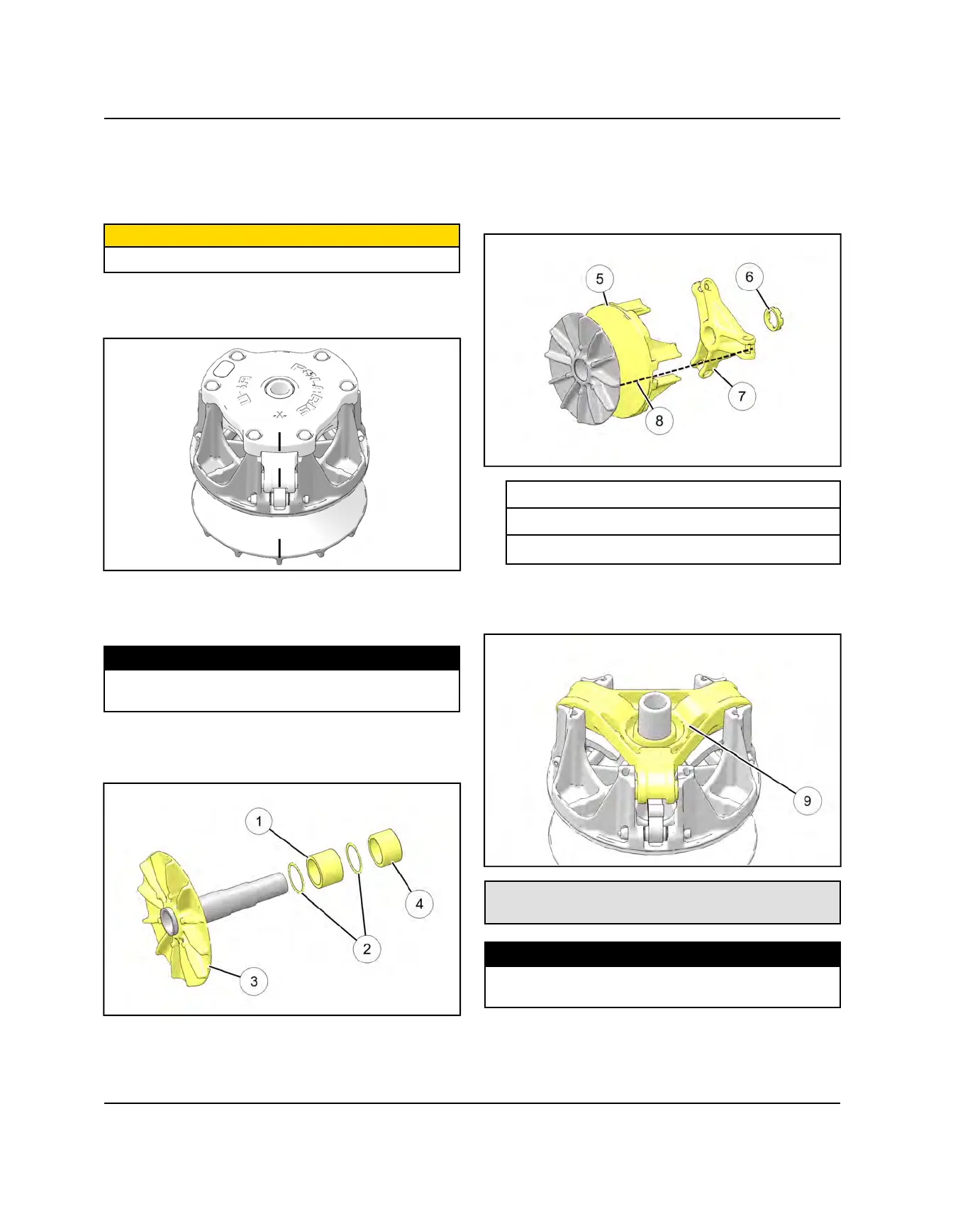
4. Apply 0.4 mL of Loctite® 620™ and 0.4 mL of
Loctite® 7088™ Primer in 90° apart in vertical stripes
to the shaft threads.
5. Install the spider assembly onto the shaft threads. Be
sure all of the alignment marks
i
are in alignment.
t
Moveable Sheave Asm
y
Jam Nut
u
Spider
6. Install clutch onto holding fixture and secure in a
bench vice. Tighten the spider
o
using Clutch Spider
Tool. Torque spider to specification.
Holding Fixture: PN 2871358-A
Clutch Spider Tool: PN 2870341
TORQUE
Spider Assembly:
290 ft-lb (393 Nm) (Apply 0.4 mL Loctite® 620™)
PVT SYSTEM

 Loading...