11.30
9929422 R02 - 2017-2019 ACE 900 Service Manual
© Copyright Polaris Industries Inc.
SWITCHES / CONTROLS
BRAKE LIGHT SWITCH
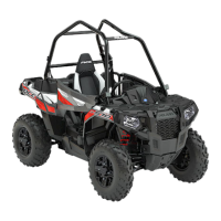
1. The brake light switch
q
is located on the front brake
line banjo bolt of the master cylinder. The brake
switch can be accessed through the right front wheel
well opening.
2. Disconnect wire harness from switch and connect an
ohmmeter across switch contacts. The reading
should be infinite (OL).
3. Apply the brake and check for continuity. If there is
no continuity or if resistance is greater than 0.5
ohms, clean the switch terminals. Re-test and
replace switch if necessary.
4. For switch replacement, refer to Chapter 10
“Brakes”.
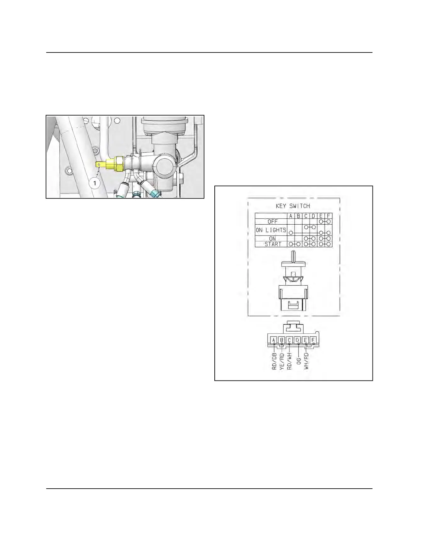
IGNITION KEY SWITCH
1. Disconnect the key switch harness by lifting the
connector lock and pulling on the connector. Do not
pull on the wiring.
2. Test between the 4 sets of outputs (OFF / ON
LIGHTS / ON / START). If any of the tests fail,
replace ignition switch assembly.
• Turn the ignition key to ON LIGHTS. There should be
continuity between switch pins A, E and F; C and D.
• Turn the ignition key to ON. There should be continuity
between pins C and D; E and F.
• Turn the ignition key to START. There should be
continuity between pins A and B; C and D; E and F.
ELECTRICAL

 Loading...