Configuration using Web Based Management and Command Line Interface
4.5 The Switch menu
SCALANCE X-300 / X-400
250 Configuration Manual, 10/2014, C79000-G8976-C187-22
●
If the link power margin enters this range, maintenance is necessary. The boundary of
the yellow area is at a link power margin of 2 dB. To ensure long-term functionality of the
system, the maintenance should be performed. If the link power margin is in the yellow
area, an event is triggered.
●
If the link power margin enters the orange range, urgent maintenance is necessary. The
boundary of the orange area is at a link power margin of 0 dB. If the link power margin is
in the orange range, an event is triggered and the FO LED of the relevant port lights up.
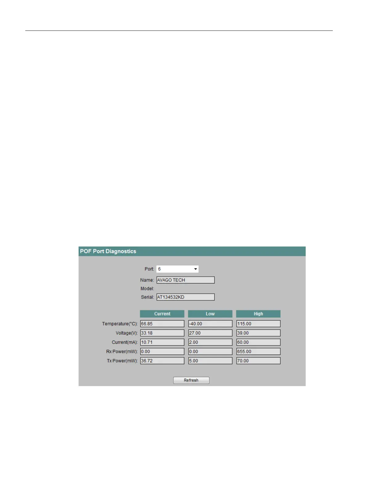
POF Diagnostics
Requirement
On this page, you run independent error diagnostics for each individual POF port. This test is
performed without needing to remove the cable, connect a cable tester or install a loopback
module at the other end.
You can only use POF diagnostics with transceivers capable of diagnostics. Devices and
modules with transceivers capable of diagnostics have the supplement "P" in the name.
 Loading...