Detailed Description
2.1 Various interface signals and functions (A2)
NC/PLC Interface Signals (Z1)
2-18 Function Manual, 08/2005 Edition, 6FC5397-0BP10-0BA0
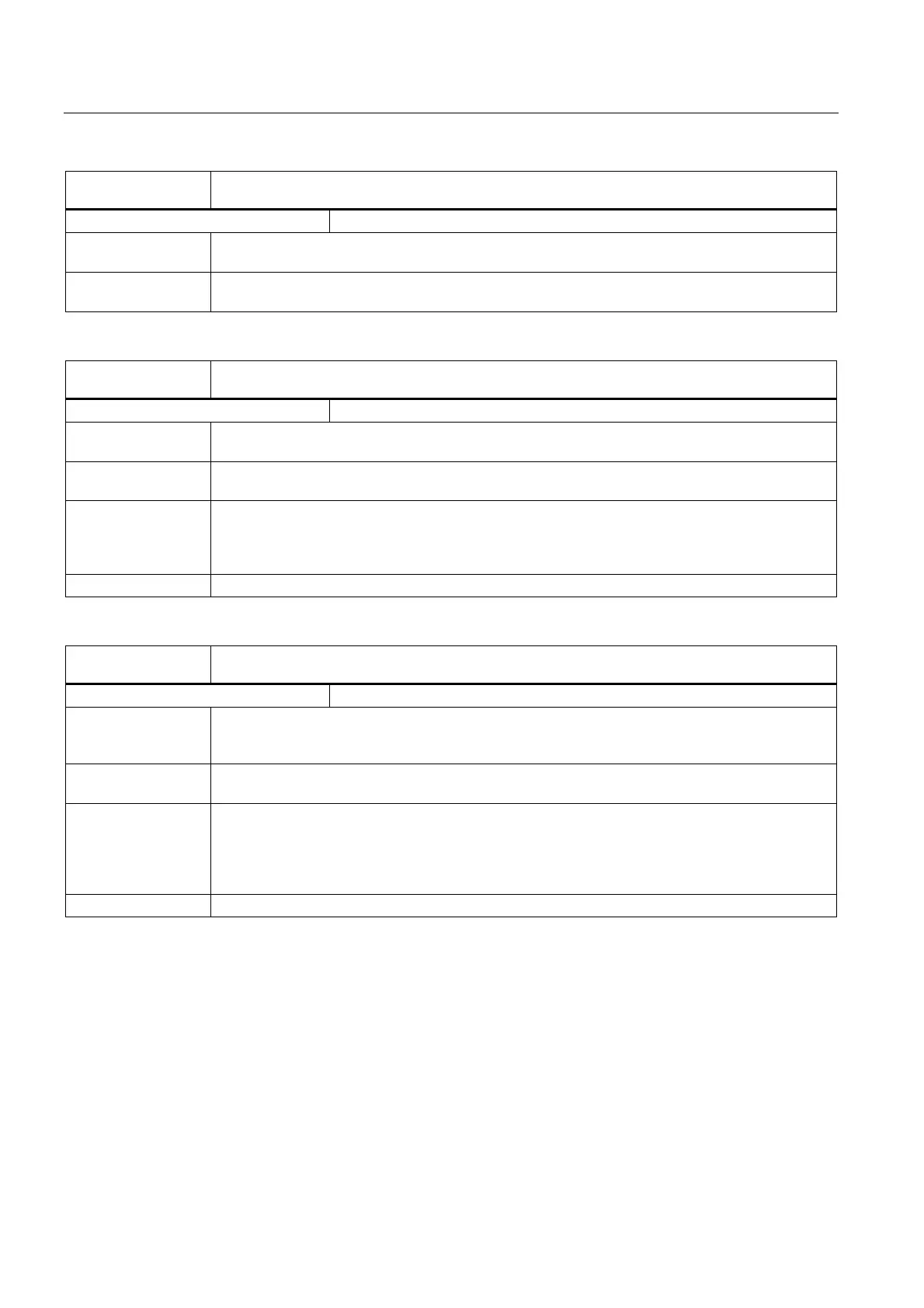
DB19
DBX20.4
Recall alarm cleared
Edge evaluation: no Signal(s) updated: cyclic
Signal state 1 or
edge change 0 → 1
Recall alarm deleted active
Signal state 0 or
edge change 1 → 0
Recall alarm deleted inactive
DB19
DBX20.6
Simulation selected
Edge evaluation: no Signal(s) updated: cyclic
Signal state 1 or
edge change 0 → 1
On entry to simulation = 1
Signal state 0 or
edge change 1 → 0
On exit from simulation = 0
Application
example(s)
Can be evaluated by machine manufacturer in order to activate the test on NC start.
The following must be set in the drive machine data:
MD1012 $MD_FUNC_SWITCH, bit 2 = 0.
Status "Ext. pulse disable active, terminal 663 open" is then not transmitted to the NC.
Corresponding to .... MD1012 $MD_FUNC_SWITCH, bit 2
DB19
DBX20.7
Switch over MCS/WCS
Edge evaluation: no Signal(s) updated: cyclic
Signal state 1 or
edge change 0 → 1
The coordinate system is switched over from workpiece coordinate system (WCS) to machine
coordinate system (MCS) or from MCS to WCS.
After it has been set, the signal is active for 1 PLC cycle.
Signal state 0 or
edge change 1 → 0
No effect
Application
example(s)
The interface signal:
DB19, DBX20.7 (change over MCS/WCS)
must be transferred to the interface signal:
DB19, DBX0.7 (actual value in WCS)
in order that the changeover becomes effective.
Corresponding to .... DB19, DBX0.7 (actual value in WCS)
 Loading...


