Detailed Description
2.3 Coordinate systems
Axis Types, Coordinate Systems, Frames (K2)
Function Manual, 08/2005 Edition, 6FC5397-0BP10-0BA0
2-23
2.3 2.3 Coordinate systems
2.3.1 Overview
Meaning
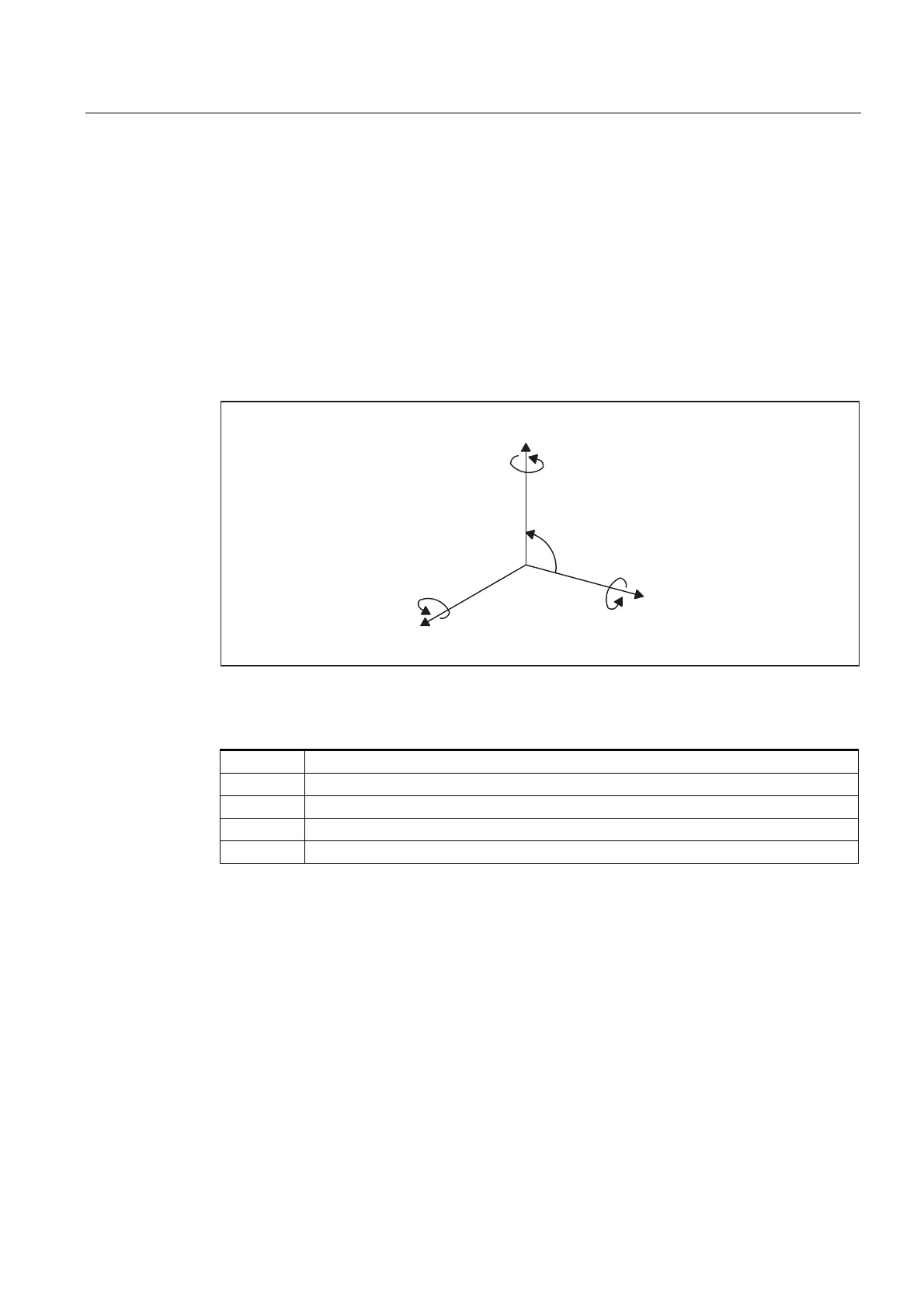
DIN 66217 stipulates that machine tools must use right-handed, rectangular (Cartesian)
coordinate systems.
$%&
;<=
&
$
%
r
;
=
<
$[HVSHUSHQGLFXODUWR
RQHDQRWKHU
5RWDU\D[HVURWDWLQJ
DERXW;<=
Fig. 2-11 Clockwise, rectangular Cartesian coordinate system
The following coordinate systems are defined:
MCS Machine Coordinat System
BCS Basic Coordinate System
BZS Basic Zero System
SZS Settable Zero System
WCS Workpiece Coordinate System
The coordinate systems are determined by the kinematic transformation and the FRAMES.
A kinematic transformation is used to derive the BCS from the MCS. If no kinematic
transformation is active, the BCS is the same as the MCS.
The basic frame maps the BCS onto the BZS.
An activated settable FRAME G54 to G599 converts the BZS to the SZS.
The WCS, which is the basis for programming, is defined by the programmable FRAME.
 Loading...


