Detailed Description
2.4 Frames
Axis Types, Coordinate Systems, Frames (K2)
Function Manual, 08/2005 Edition, 6FC5397-0BP10-0BA0
2-39
[
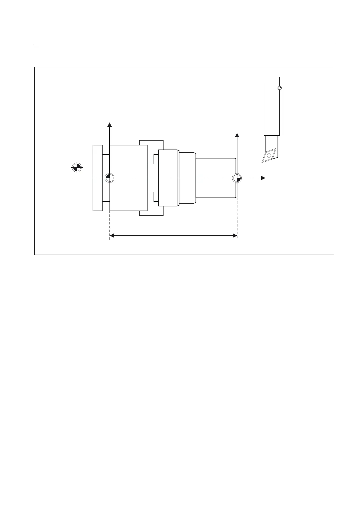
3B$&7)5$0(
]
:&6
0&6
5HIHUHQFHSRLQW
7RROUHIHUHQFH
SRLQW
The position of the reference point R is defined by cam switches. The reference point must
be approached each time the control is activated. The control can only then work with the
measuring system and transfer all position values to the coordinate systems.
The machine zero M defines the machine coordinate system MCS. All other reference points
refer to the machine zero.
The workpiece zero W defines the workpiece coordinate system in relation to the machine
zero. The programmed part-program blocks are executed in the workpiece coordinate
system.
The toolholder reference point is located on the toolholder locator. By entering the tool
lengths, the control calculates the distance between the tool tip (TCP Tool Center Pos) and
the toolholder reference point.
2.4.2 Frames
A frame is a structure, which contains a value for the translation, fine offset, rotation (only for
geometry axes), scaling and mirroring for each axis. Activating a frame causes a static
coordinate transformation to be carried out via a defined calculation rule.
 Loading...


