247
To make a wipe pattern like a window blind
(Pairing)
Set the [Pairing] button to the on state and set the
foll
owing parameter.
To add modulation to a pattern (Modulation)
In the [Modulation] group, select a modulation type.
H: Modulate a pattern in the horizontal direction.
V: Modul
ate a pattern in the vertical direction.
The modulation is set to a sine wave.
Set the following parameters.
Image Effect
Overview
Image effect is a function used to apply a DME effect to
the signal selected on the background A bus or B bus.
• Setting the image effect fun
ction introduces a one-
frame delay in the image.
• In flip-flop mode, interchanging the background A bus
a
nd B bus signals also interchanges their image effect
settings at the same time.
DME restrictions
• To use the DME function, the XKS-G1600 GPU Pack
(option) and XZS-G1610 3D DME License (option) are
required.
When the system signal forma
t is 2160P, the DME
function must be enabled for use.
For details about setting GPU functions, see “Setting a
GPU” (page 364).
• The number of DME channels t
hat can be used will
vary, depending on the system signal format and the
DME enhanced function mode setting.
For details, see “DME channels” (page 195).
• The image effect function cannot be set when a
backgr
ound DME wipe is set.
Number of DME channels that can be used
s
imultaneously
DMEs can be used in up to two locations simultaneously
o
n a single switcher bank (processed key or image effect).
The number of DME channels that
can be used on a key
depends on the image effect use, as given below.
When not using the image effect function:
One DME channel on each of two keys, or one to four
D
ME channels on a single key can be used.
When using the image effect fu
nction on background A or
B:
One DME channel on a single key only can be used.
When using the image effe
ct function on both
background A and B:
DMEs cannot be used on keys.
• In multi program 2 mode, DMEs can be used in up to
t
wo locations (main and sub).
• When M/E split is enabled, one DME channel can be
u
sed on each of the two sub blocks.
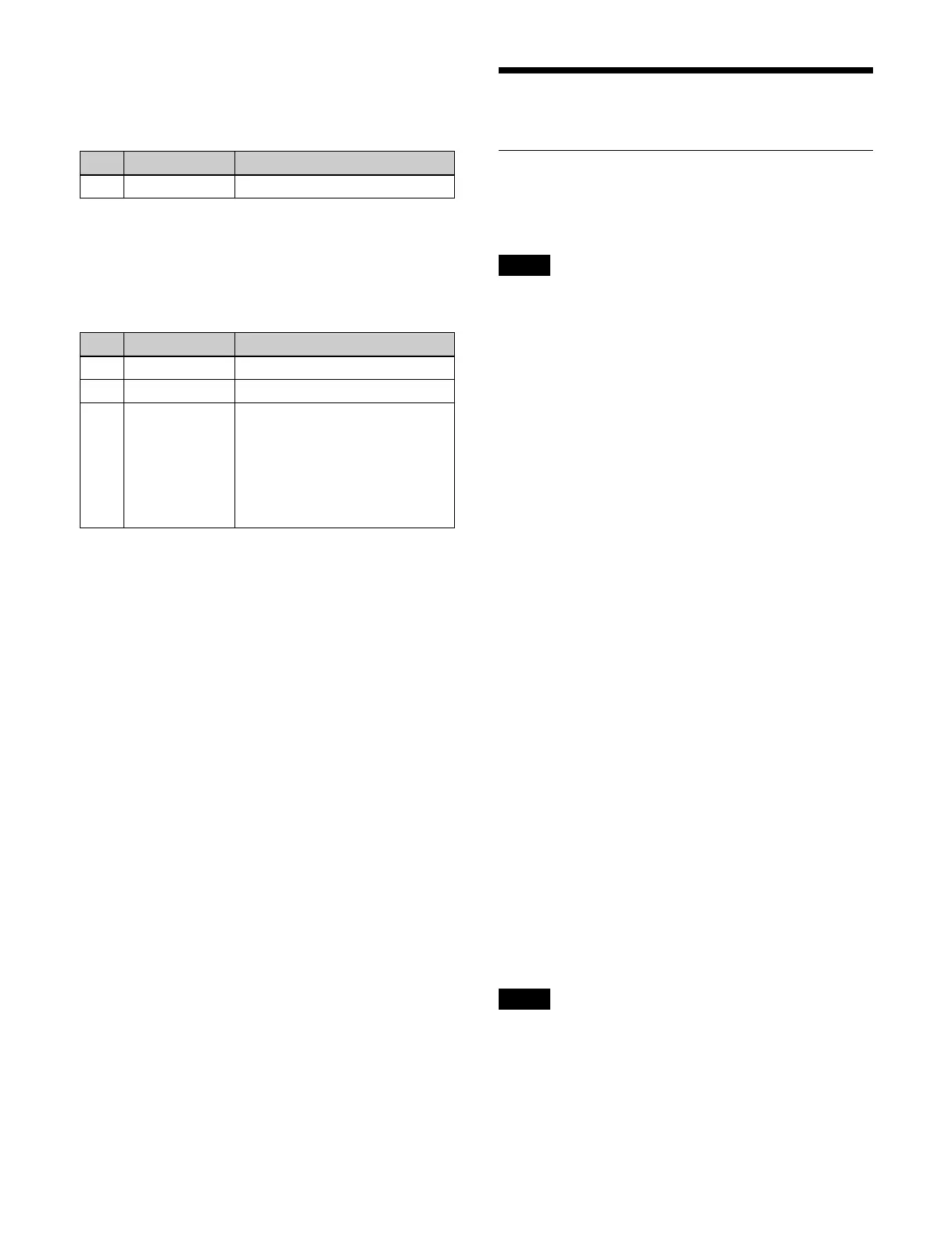
No. Parameter Adjustment
1 Width Width
No. Parameter Adjustment
1 Amplitude Amplitude of modulation
2 Frequency Frequency of modulation
3 Speed Speed of ripples
• Negative values create waves
in th
e down, left, and
counterclockwise directions.
• Positive values create waves in
t
he up, right, and clockwise
directions.
Notes
Notes
 Loading...


