447
Configuring Network
Settings
Setting the Host Name of the
Switcher
The host name setting is linked to the system name setting
in the System Configuration > SNMP > Common menu
(20701.11).
1
Open the System Configuration > Network >
Network Settings menu (20201.11).
2
Press the [Hostname] button and enter a host name
(up to 63 characters) using the keyboard.
3
Press [OK].
4
Press the [Apply] button.
To return to the previous setting
Press the [Clear] button, check the message, then
press [OK].
5
Check the message, then press [OK].
Setting the Network Interface
You can configure the following six types of network
interface.
• Standard interface 1 (STD 1):
LAN 1 connector (
f (see page 58) on rear of switcher)
settings
• Standard interface 2 (STD 2):
LAN 2 connector (
g (see page 58) on rear of switcher)
settings
• Expansion interface 1 (OPT 1):
Network expansion 1 connector
1)
(r (see page 59) on
rear of switcher) settings
• Expansion interface 2 (OPT 2):
Network expansion 2 connector
1)
(q (see page 59) on
rear of switcher) settings
• Expansion interface 3 (OPT 3):
Network expansion 3 connector
1)
(p (see page 59) on
rear of switcher) settings
• Expansion interface 4 (OPT 4):
Network expansion 4 connector
1)
(o (see page 59) on
rear of switcher) settings
1) Can be used when a network card is installed in the PCIe slot of the
switcher.
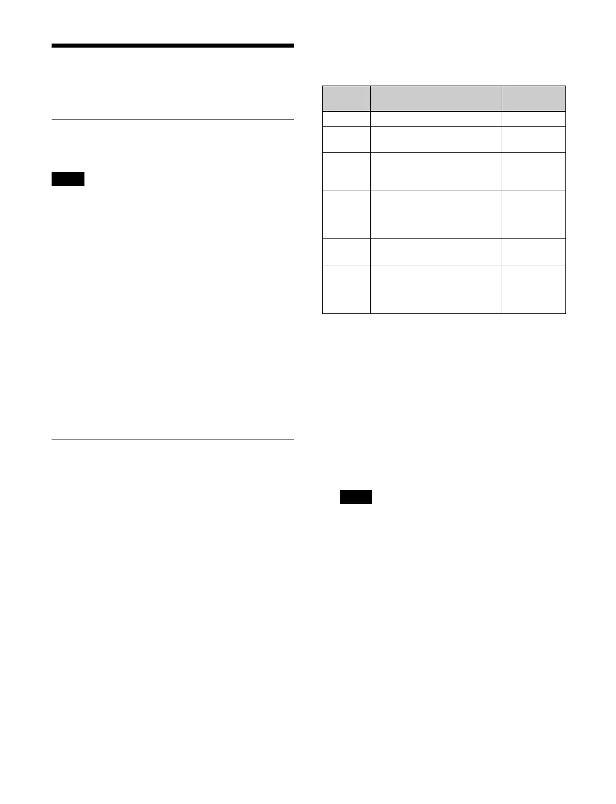
The switcher LAN connector and configurable LAN
types supported by each network interface are shown
below.
a) Number corresponding to the description of parts on the rear of the
switcher.
To set standard interface 1 (STD 1)
1
Open the System Configuration > Network >
Network Settings menu (20201.11).
2
Select [STD1].
3
Press the [Edit] button.
The [Standard Network I/F 1 Settings] window
appea
rs.
The standard interface addresses
can only be set
manually.
4
Press the [Address] button for [IPv4] and enter an
address using the keyboard.
5
Press the [Prefix Length] button for [IPv4] and enter
a prefix length in the numeric keypad window.
6
Press [OK].
7
Press the [Apply] button.
To return to the previous setting
Press the [Clear] button, check t
he message, then
press [OK].
8
Check the message, then press [OK].
Note
Network
I/F
Configurable LAN Connector
a)
STD 1 • Control LAN (Ctrl LAN) f
STD 2 • Utility LAN 1 (Util LAN 1)
• No setting (Off)
g
OPT 1 • For control LAN redundancy
(Ctrl LAN Redu
ndant)
• No setting (Off)
r
OPT 2 • Utility LAN 2 (Util LAN 2)
• For utility LAN 1 redundancy
(Util LAN 1 Red
undant)
• No setting (Off)
q
OPT 3 • User LAN 1 (User LAN 1)
• No setting (Off)
p
OPT 4 • User LAN 2 (User LAN 2)
• For user LAN 1 redundancy
(User LAN 1 Redu
ndant)
• No setting (Off)
o
Note
 Loading...


