OF40/S0 "KS"
('OS)
MODEL
1S
• The flywheel magneto has been changed
in
shape.
• The key groove width in the flywheel magneto has been changed.
• The crankshaft key width has been changed.
• The flywheel side of the crankshaft has been changed
in
machining.
• The flywheel bolt has been changed in length.
5mm--t4mm
~r-
BATTERY CHARGING SYSTEM
OUTLINE
Key
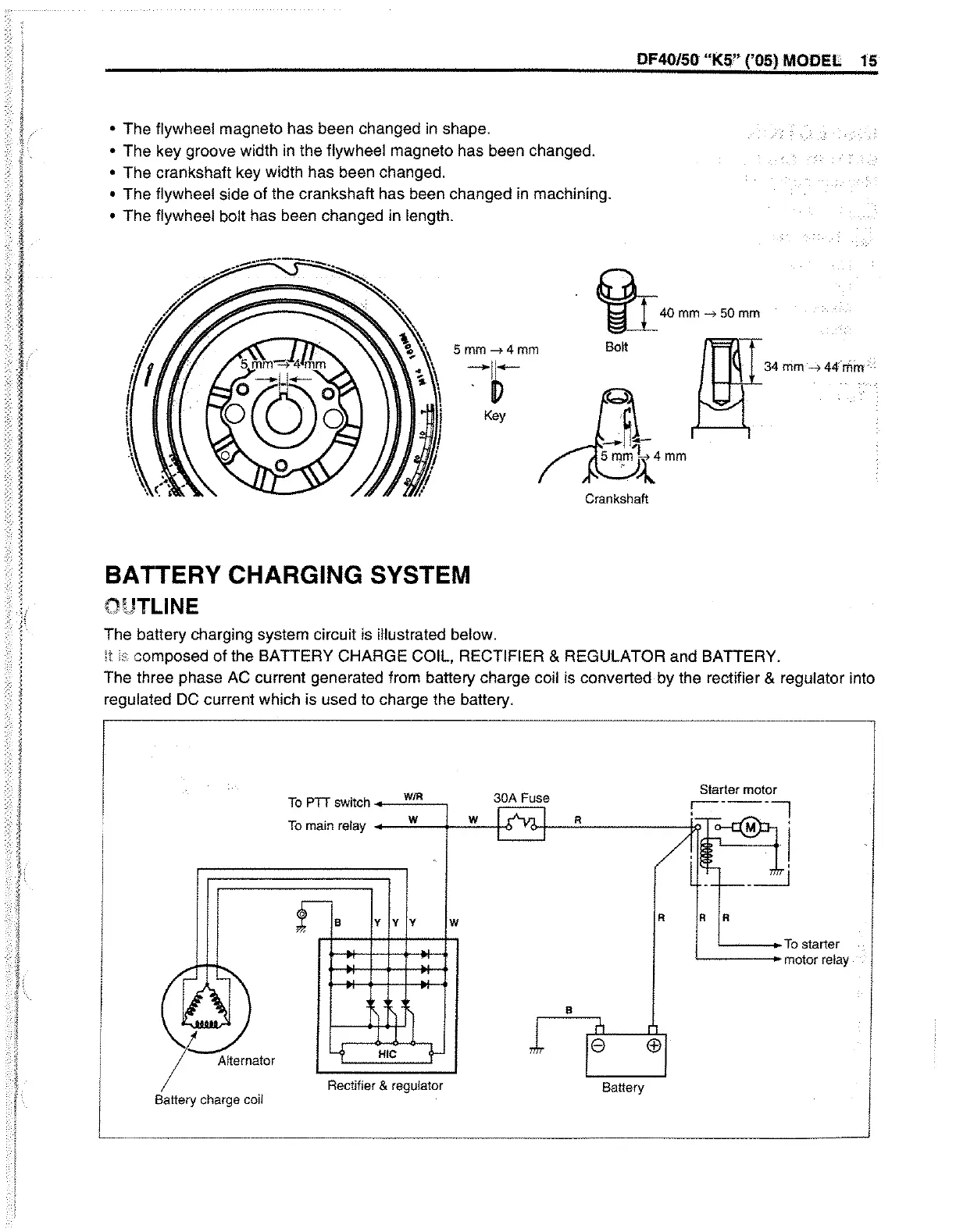
The battery charging system circuit is illustrated below.
~40mm->50mm
Bo~
I I
Crankshaft
it composed
of
the BATTERY CHARGE COIL, RECTIFIER & REGULATOR and BATTERY.
The three phase AC current generated from battery charge coil is converted by the rectifier & regulator into
regulated
DC
current which is used to charge the battery.
l
To
PTT
switch .....
_W"'IR.:.:.....-,
30A Fuse
To
main
relay
.......
-"w_+-_w"-+6
R
y y y
W
B
Alternator
Rectifier
&
regulator
R
Battery
Starter
motor
:----1
M .
'----+
I
R R
L
.-.:::==:TO
starter
motor
relay
~----------------------------------------------------~
 Loading...


