3-11 ENGINE CONTROL SYSTEM
IGNITION CONTROL SYSTEM
OUTLINE
Sensors at specific points on the engine monitor current engine conditions and send signals to the ECM.
Based on these signals, the ECM determines the optimum ignition timing and releases voltage to the igni-
tion coils.
IGNITION SYSTEM
The ignition system used by the DF40/DF50 is a fully transistorized, electronic microcomputer timing ad-
vanced type.
On this system, power is totally supplied from the battery with the ECM controlling all ignition timing func-
tions.
The ignition system is composed of the ignition coil, spark plug and components for system control (ECM,
sensor,switch etc.)
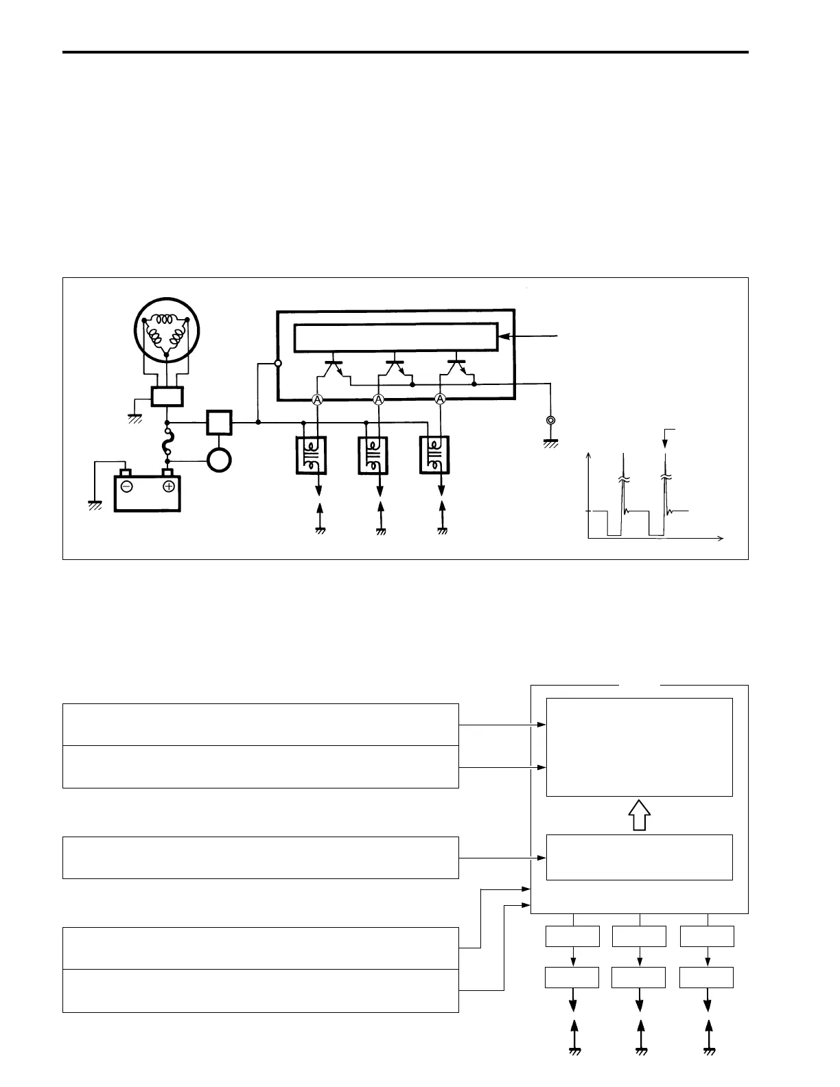
When the ignition switch is “ON”, battery voltage (12V) is applied to the circuit as shown in the illustration.
At the calculated time of ignition, the transistor in the ECM turns “OFF”, breaking the ground circuit.
In this way, a mutual induction high voltage occurs in the ignition coil secondary side and spark is generated.
Basic sensors
Compensating sensors
Switches
Spark plug
MAP sensor :
Informs ECM of intake manifold pressure.
CKP sensor :
Informs ECM of engine speed and crankshaft angle.
Cylinder temperature sensor :
Informs ECM of cylinder temperature.
CTP switch :
Informs ECM of throttle position (open / closed).
Ignition switch :
Informs ECM of “START” signal.
Ignition timing is deter-
mined by a digital map de-
signed in relation to intake
manifold pressure and en-
gine speed.
ECM
Ignition timing compensa-
tion.
Signal
Ign.coil
Signal
Ign.coil
Signal
Ign.coil
(Voltage)
Spark timing
12V
A terminal voltage
(Time)
Sensor/switch
signal input
ECM
CPU
ECM
main
relay
Ignition
switch
Battery
30A fuse
Rectifier &
regulator
Battery
charge
coil
Ignition
coil
Spark
plug
 Loading...


