8-M18
ME8200, ME9000, WSM
HYDRAULIC SYSTEM
5. HYDRAULIC TRAILER BRAKE VALVE
[1] STRUCTURE
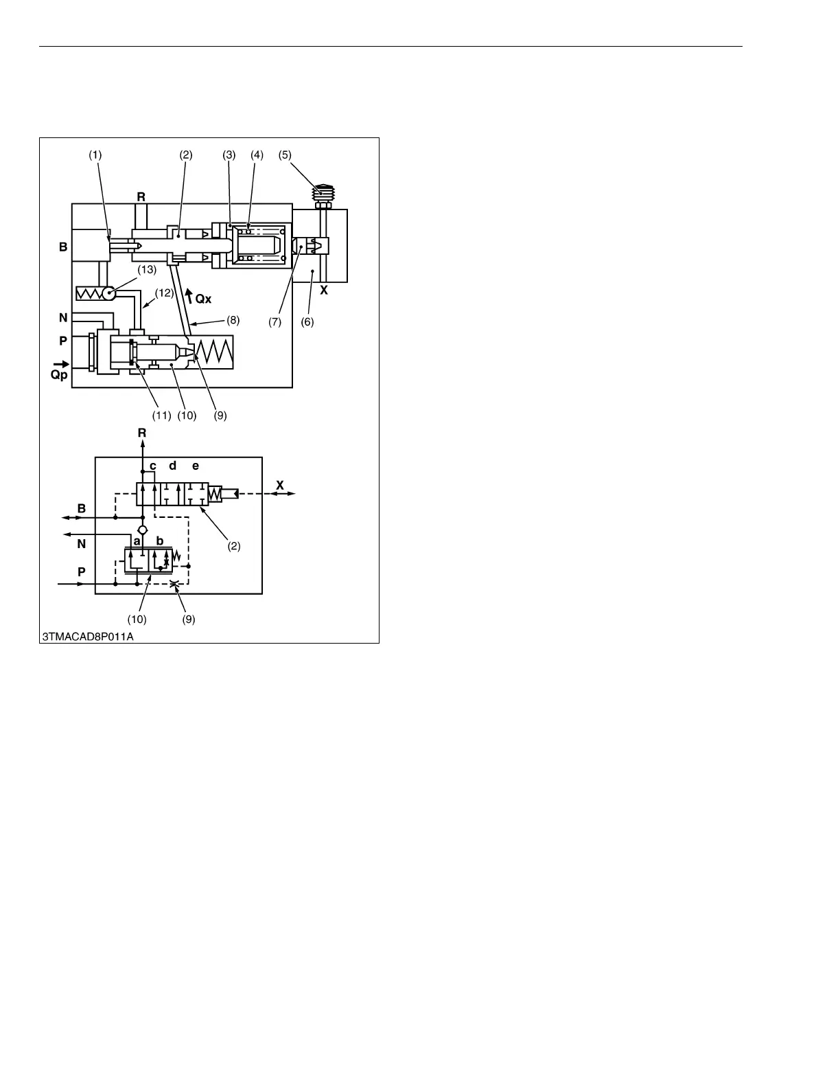
■ Main Elements
• Flow control valve (10) with throttle (9) and restrictor
(11) : for controlling the delivery flow Qp and for
regulating the fluid flow for the trailer brake.
• Control spool (2) with piston surface (1) : for
controlling the flow control valve (10) and regulating
the trailer braking pressure.
• Check valve (13) : prevents oil from flowing back from
the brake line B to port N.
• Pressure relief element (3) with pre-loaded spring (4)
: for limiting the trailer braking pressure.
• Control head (6) with piston (7) and bleed valve (5) :
for operating the trailer brake valve through the tractor
brake line.
W1016170
(1) Piston Surface
(2) Control Spool
(3) Pressure Relief Element
(4) Spring
(5) Bleed Valve
(6) Control Head
(7) Piston
(8) Bore
(9) Throttle
(10) Flow Control Valve
(11) Restrictor
(12) Bore
(13) Check Valve
P : Port for 3P Hydraulic Pump
N : Port for 3P Control Valve
B : Port for Trailer Brake
(Connected to Coupler)
R : Port for Reservoir
(Transmission Case)
X : Port for Tractor Service
Brake (Connected to Pilot
Pipe)
Qp :Delivery Flow
Qx :Control Flow
 Loading...