8-M25
ME8200, ME9000, WSM
HYDRAULIC SYSTEM
[2] POSITION CONTROL
Position control is a system to raise and lower the implement proportionally to the movement of the position control
lever. With this system, the implement can be raised or lowered to any position desired by changing the position of
the control lever and fine adjustment is also easy. When using the position control, the draft control lever should be
set to the lowest position.
■ Raising
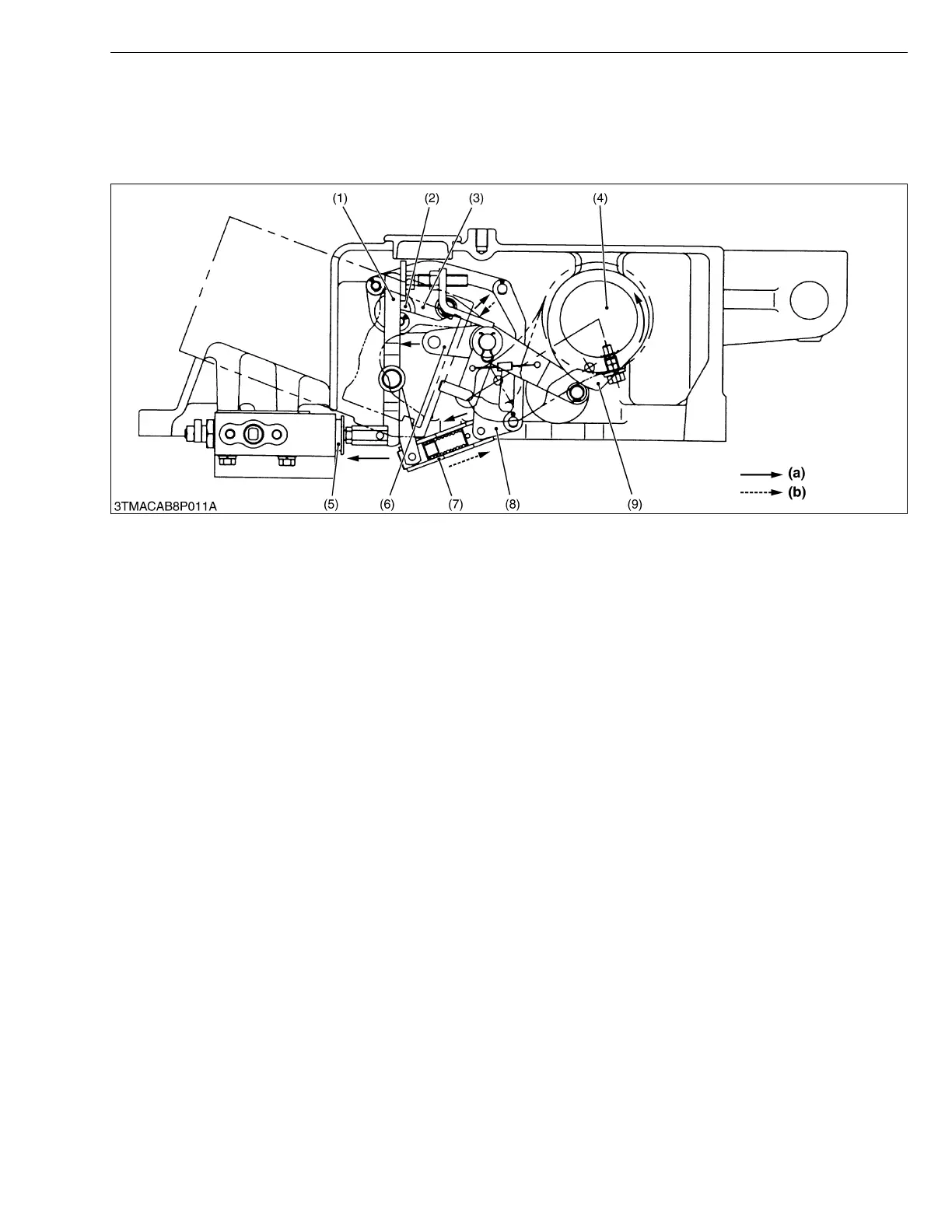
1. When the position control lever is moved to the Raising direction, the position control shaft (2) rotates clockwise
to move the position connector (3) to the left.
2. Since the position balancer (6) is prevented by the position cam (9) from moving, the connector (8) rotates
clockwise as the position connector (3) moves. Thereby the holder (7) and spool retainer (1) are pushed against
the spool (5), and the spool (5) is forced in the control valve. As a result, a Raising circuit is formed.
3. When the lift arm moves upward, the hydraulic arm shaft (4) and position cam (9) rotate counterclockwise. As a
result, the position balancer (6) is also rotated counterclockwise. Accordingly, as the connector (8) does not press
the spool retainer (1), the spool (5) is forced out by the return spring in the control valve (feedback mechanism).
4. When the spool (5) returns to the neutral position, the lift arms stop rising. This results in raising of the lift arm in
proportion to the movement of the position control lever.
■ Lowering
1. When the control lever is moved to the Lowering direction, the position control shaft (2) rotates counterclockwise
to move the position connector (3) to the right.
2. As the position connector (3) moves, the connector (8) does not press the spool retainer (1) and the spool (5) is
forced out by the return spring in the control valve. As a result, a Lowering circuit is formed.
3. When the lift arms move downward, the hydraulic arm shaft (4) and position cam (9) rotate clockwise, causing the
position balancer (6) and connector (8) to press the holder (7) and spool retainer (1). Thereby, the spool (5) is
forced in (feedback mechanism).
4. When the spool (5) returns to the neutral position, the lift arms stop rising. This results in lowering of the lift arms
in proportion to the movement of the position control lever.
(1) Spool Retainer
(2) Position Control Shaft
(3) Position Connector
(4) Hydraulic Arm Shaft
(5) Spool
(6) Position Balancer
(7) Holder
(8) Connector
(9) Position Cam
(a) Motion for Raising
(b) Motion for Feedback