9-S25
ME8200, ME9000, WSM
ELECTRICAL SYSTEM
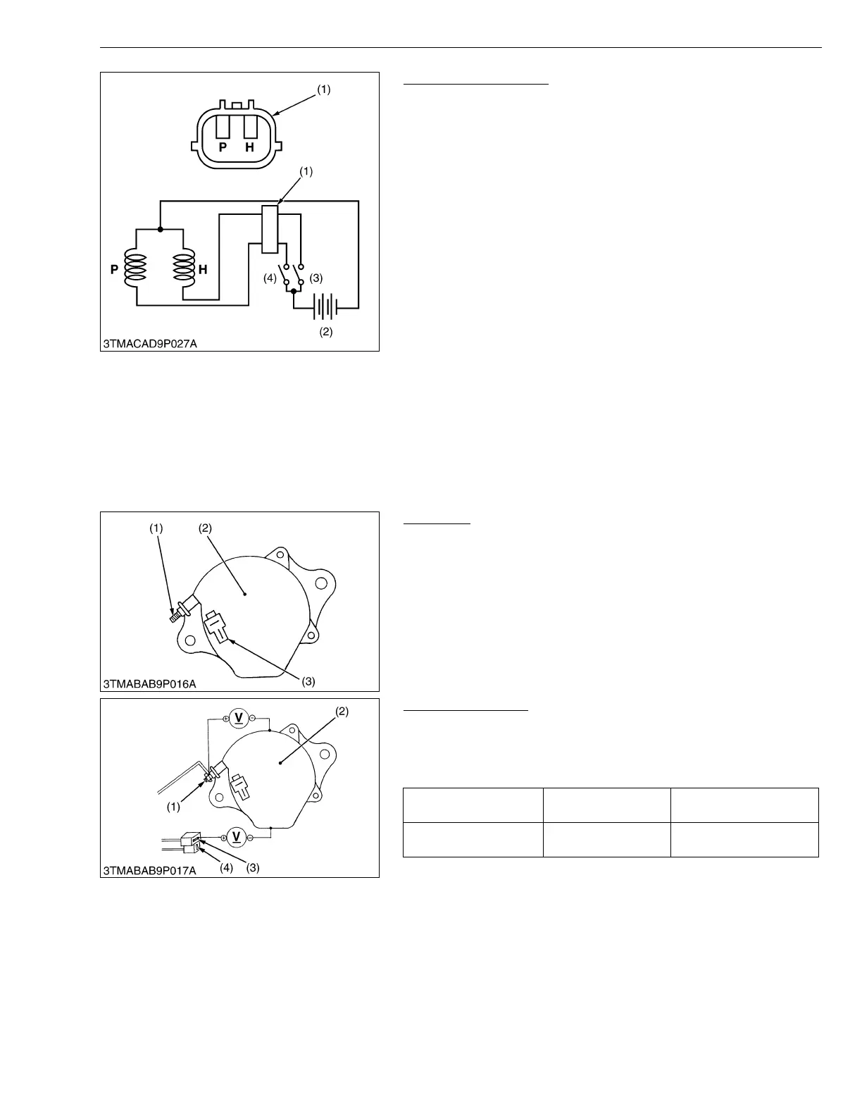
Engine Stop Solenoid
1. Remove the engine stop solenoid from the engine.
2. Connect the jumper leads from the pulling coil P terminal to the
switch (3), and from switch (3) to the battery positive terminal.
3. Connect the jumper leads from the holding coil H terminal to the
switch (4), and from switch (4) to the battery positive terminal.
4. Connect the jumper leads from the engine stop solenoid body to
the battery negative terminal.
5. When switch (4) is turn on, the plunger pull into the solenoid body
and then turn off the switch (4), the plunger comes out.
6. Turn on the switch (3) then turn on the switch (4), the plunger pull
into the solenoid body and it keep in holding position after turn off
the switch (4).
7. If the plunger is not attracted, the engine stop solenoid is faulty.
• Never apply the current for pulling coil more than two
seconds when inspecting.
W1019594
[4] CHARGING SYSTEM
(1) Checking
Alternator
1. Disconnect the 2P connector (3) from alternator after turning the
main switch OFF.
2. Perform the following checkings.
W1018175
Connector Voltage
1. Turn the main switch OFF. Measure the voltage between the B
terminal (1) and the chassis.
2. Turn the main switch ON. Measure the voltage between the IG
terminal (3) and the chassis.
W1018279
(1) Connector
(2) Battery
(3) Switch for Holding Coil
(4) Switch for Pulling Coil
P : Terminal for Pulling Coil
H : Terminal for Holding Coil
(1) B Terminal
(2) Alternator
(3) 2P Connector
Voltage
(Main switch at OFF)
B terminal – Chassis Approx. battery voltage
Voltage
(Main switch at ON)
IG terminal – Chassis Approx. battery voltage
(1) B Terminal
(2) Alternator
(3) IG Terminal
(4) L Terminal
 Loading...