10-S15
ME8200, ME9000, WSM
CABIN
5. CHECKING AND CHARGING REFRIGERANT CYCLE
[1] CHECKING WITH MANIFOLD GAUGE
• The gauge indications described in the following testing are those taken under the same condition, so it
should be noted that the gauge readings will differs somewhat with the ambient conditions.
Condition
• Ambient temperature : 30 to 35 °C (86 to 95 °F)
• Engine speed : Approx. 1500 min
−1
(rpm)
• Temperature control lever : Maximum cooling position
• Blower switch : HI position
Manifold Gauge Connecting and Test Preparation
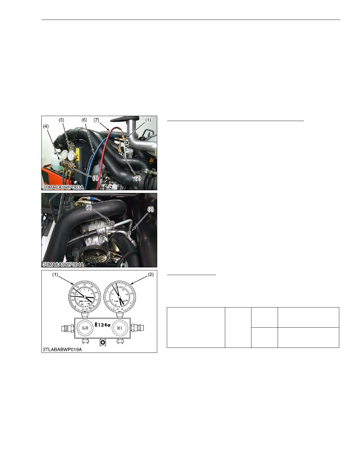
1. Close the manifold gauge HI and LO pressure side valve (3), (4)
tightly.
2. Connect the charging hose (7) (red) to the HI pressure side
charging valve (1) and connect the charging hose (6) (blue) to the
LO pressure side charging valve (2).
• Be sure to drive out the air in the charging hoses at the
manifold gauge connection end by utilizing the refrigerant
pressure in the refrigerating cycle.
3. Start the engine and set at approx. 1500 min
−1
(rpm).
4. Turn on the A/C switch and set the temperature control lever to
maximum cooling position.
5. Set the blower switch to HI position.
W1015662
Normal Operating
If the refrigerating cycle is operating normally, the reading at the
LO pressure side (1) should be generally by around 0.15 to 0.2 MPa
(1.5 to 2.0 kgf/cm
2
, 21 to 28 psi) and that at the HI pressure side (2)
around 1.27 to 1.66 MPa (13 to 17 kgf/cm
2
, 185 to 242 psi).
W1015870
(1) HI Pressure Side Charging Valve
(2) LO Pressure Side Charging Valve
(3) HI Pressure Side Valve
(4) LO Pressure Side Valve
(5) Manifold Gauge
(6) Charging Hose (Blue)
(7) Charging Hose (Red)
Gas pressure
Factory
spec.
Low
pressure
side
0.15 to 0.20 MPa
1.5 to 2.0 kgf/cm
2
21 to 28 psi
High
pressure
side
1.27 to 1.66 MPa
13 to 17 kgf/cm
2
185 to 242 psi
(1) LO Pressure Side (2) HI Pressure Side
 Loading...