8-S9
ME8200, ME9000, WSM
HYDRAULIC SYSTEM
(2) Hydraulic Shuttle System
(A) System Pressure
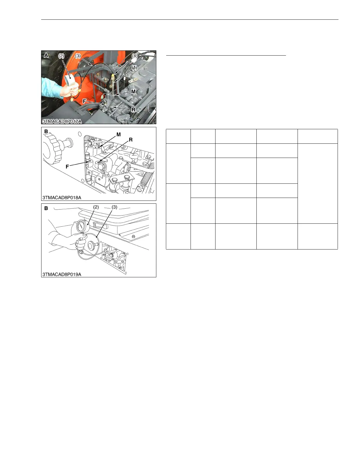
Checking of Shuttle Valve System Pressure
1. Remove the floor mat, housing cover, seat, fenders (RH and LH)
and center frame.
2. Remove the each plugs of F, R, M and set the adaptor D (1),
threaded joint (4), cable (3), and pressure gauge (Code No. :
07916-52961) (2).
3. Start the engine and measure the pressure of each port and each
shuttle lever position as the pressure table.
Condition
• Engine speed..... Approx. 2800 min
-1
(rpm)
• Oil temperature...45 to 55 °C (113 to 131 °F)
• Use valve adaptor (see page G-60) to inspect the port F and
R for the cabin type.
• Pressure gauge is 5 MPa (50 kgf/cm
2
, 700 psi) full scale.
• Apply Three Bond 1324N or equivalent to the plugs F, R and
M, when install them.
W1013770
Shuttle
Lever
Clutch
Pedal
F port pressure R port pressure M port pressure
Forward
Fully
pressed
00
2.45 to 2.55 MPa
25.0 to
26.0 kgf/cm
2
355 to 370 psi
Free
1.6 to 1.9 MPa
13.6 to
19.4 kgf/cm
2
232 to 276psi
0
Reverse
Fully
pressed
00
Free 0
1.6 to 1.9 MPa
13.6 to
19.4 kgf/cm
2
232 to 276psi
Neutral – 0 0
0.26 to 0.28 MPa
2.7 to
2.9 kgf/cm
2
38 to 41 psi
(1) Adaptor D
(2) Pressure Gauge
(3) Cable
(4) Thread Joint
Plug F : Operation Oil Pressure
(For Forward)
Plug R : Operation Oil Pressure
(For Reverse)
Plug M : Operation Oil Pressure
(For Modulation Valve)
A : ROPS Type
B : CABIN Type
 Loading...