32.12
•
Prior to installation, carefully press back the
brake piston using an Allen key with T-bar han-
dle, for example.
•
Use cranked-tip snap-ring pliers to install the re-
taining ring, and check that the ring is seated
correctly.
•
Apply a light coat of Optimoly MP 3 to the pres-
sure pin (arrow) on the lever.
e Attention:
When installing the brake lever, make sure that the
metal tab on the brake-light switch is correctly posi-
tioned (otherwise switch will not work).
•
Integral ABS Fill and bleed front control circuit
(
a 34.20).
•
Adjust blow-by clearance at handlebar fitting for
brake.
•
Fully assemble the fitting.
X Tightening torque:
Hand lever bearing screw............................. 11 Nm
(Tuflok Blue thread-locking compound; screw can
be released and tightened a number of times)
Adjusting blow-by clearance at handlebar fitting
for brake
•
Remove cover from throttle-cable relay.
•
Remove the lower section of the brake lever fit-
ting.
•
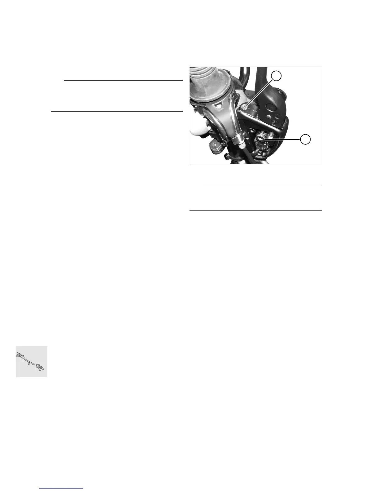
Back off adjusting screw (1).
L Note:
Thread is secured with Loctite, if necessary heat
slightly prior to facilitate removal.
•
Remove pivot screw (2) of lever and remove the
lever.
•
Clean and degrease the threads of the adjusting
screw.
•
Coat the threads of the adjusting screw with
Loctite 648 or Loctite 270 and screw it a few
turns into the lever.
•
Apply a light coat of Optimoly MP 3 to the pres-
sure pin of the adjusting screw.
•
Install the lever, making sure that the metal tab
on the microswitch is correctly positioned.
•
Tighten the adjusting screw until the lever has
zero play.
•
Tighten the adjusting screw another full turn.
•
Apply sealing lacquer to the adjusting screw.
•
Fully assemble the fitting.
X Tightening torque:
Hand lever screw bearing (2) ....................... 11 Nm
(Tuflok Blue thread-locking compound; screw can
be released and tightened a number of times)
R21340050
1
2
 Loading...