Safety
information
Product
information
Mechanical
installation
Electrical
installation
Getting
started
Basic
parameters
Running
the motor
Optimization
NV Media Card
Operation
Onboard
PLC
Advanced
parameters
Technical
data
Diagnostics
UL listing
information
102 Unidrive M702 User Guide
Issue Number: 3
7 Running the motor
This chapter takes the new user through all the essential steps to
running a motor for the first time, in each of the possible operating
modes.
For information on tuning the drive for the best performance, see
Chapter 8 Optimization on page 118.
7.1 Quick start connections
7.1.1 Basic requirements
This section shows the basic connections which must be made for the
drive to run in the required mode. For minimal parameter settings to run
in each mode please see the relevant part of section 7.3 Quick start
commissioning / start-up on page 107.
Table 7-1 Minimum control connection requirements for each
control mode
Table 7-2 Minimum control connection requirements for each
mode of operation
Speed feedback
Suitable devices are:
• Incremental encoder (A, B or F, D with or without Z)
• Incremental encoder with forward and reverse outputs (F, R with or
without Z)
• SINCOS encoder (with, or without Stegmann Hiperface, EnDat or
SSI communications protocols)
• BiSS absolute encoder
• EnDat absolute encoder
• Resolver
Speed and position feedback
Suitable devices are:
• Incremental encoder (A, B or F, D with or without Z) with
commutation signals (U, V, W)
• Incremental encoder with forward and reverse outputs (F, R with or
without Z) and commutation outputs (U, V, W)
• SINCOS encoder (with Stegmann Hiperface, EnDat or SSI
communications protocols)
• BiSS absolute encoder
• EnDat absolute encoder
• Resolver
7.2 Changing the operating mode
Changing the operating mode returns all parameters to their default
value, including the motor parameters. User Security Status (Pr 00.049)
and User Security Code (Pr 00.034) are not affected by this procedure).
Procedure
Use the following procedure only if a different operating mode is
required:
1. Enter either of the following values in Pr mm.000, as appropriate:
1253 (50 Hz AC supply frequency)
1254 (60 Hz AC supply frequency)
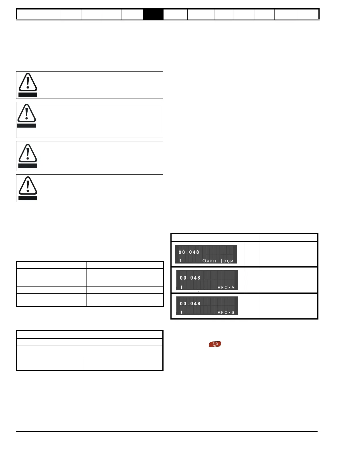
2. Change the setting of Pr 00.048 as follows:
The figures in the second column apply when serial communications are
used.
3. Either:
• Press the red reset button
• Toggle the reset digital input
• Carry out a drive reset through serial communications by setting
Pr 10.038 to 100 (ensure that Pr. mm.000 returns to 0).
Ensure that no damage or safety hazard could arise from the
motor starting unexpectedly.
The values of the motor parameters affect the protection of
the motor.
The default values in the drive should not be relied upon.
It is essential that the correct value is entered in Pr 00.046
Rated Current. This affects the thermal protection of the
motor.
If the drive is started using the keypad it will run to the speed
defined by the keypad reference (Pr 01.017). This may not
be acceptable depending on the application. The user must
check in Pr 01.017 and ensure that the keypad reference
has been set to 0.
If the intended maximum speed affects the safety of the
machinery, additional independent over-speed protection
must be used.
Drive control method Requirements
Terminal mode
Drive enable
Speed / Torque reference
Run forward / Run reverse
Keypad mode Drive enable
Serial communications
Drive enable
Serial communications link
Operating mode Requirements
Open loop mode Induction motor
RFC – A mode
(with speed feedback)
Induction motor with speed feedback
RFC – S mode (with speed and
position feedback)
Permanent magnet motor with speed
and position feedback
Pr 00.048 setting Operating mode
1 Open-loop
2RFC-A
3RFC-S

 Loading...


