Safety
information
Product
information
Mechanical
installation
Electrical
installation
Getting
started
Basic
parameters
Running
the motor
Optimization
NV Media Card
Operation
Onboard
PLC
Advanced
parameters
Technical
data
Diagnostics
UL listing
information
Unidrive M702 User Guide 255
Issue Number: 3
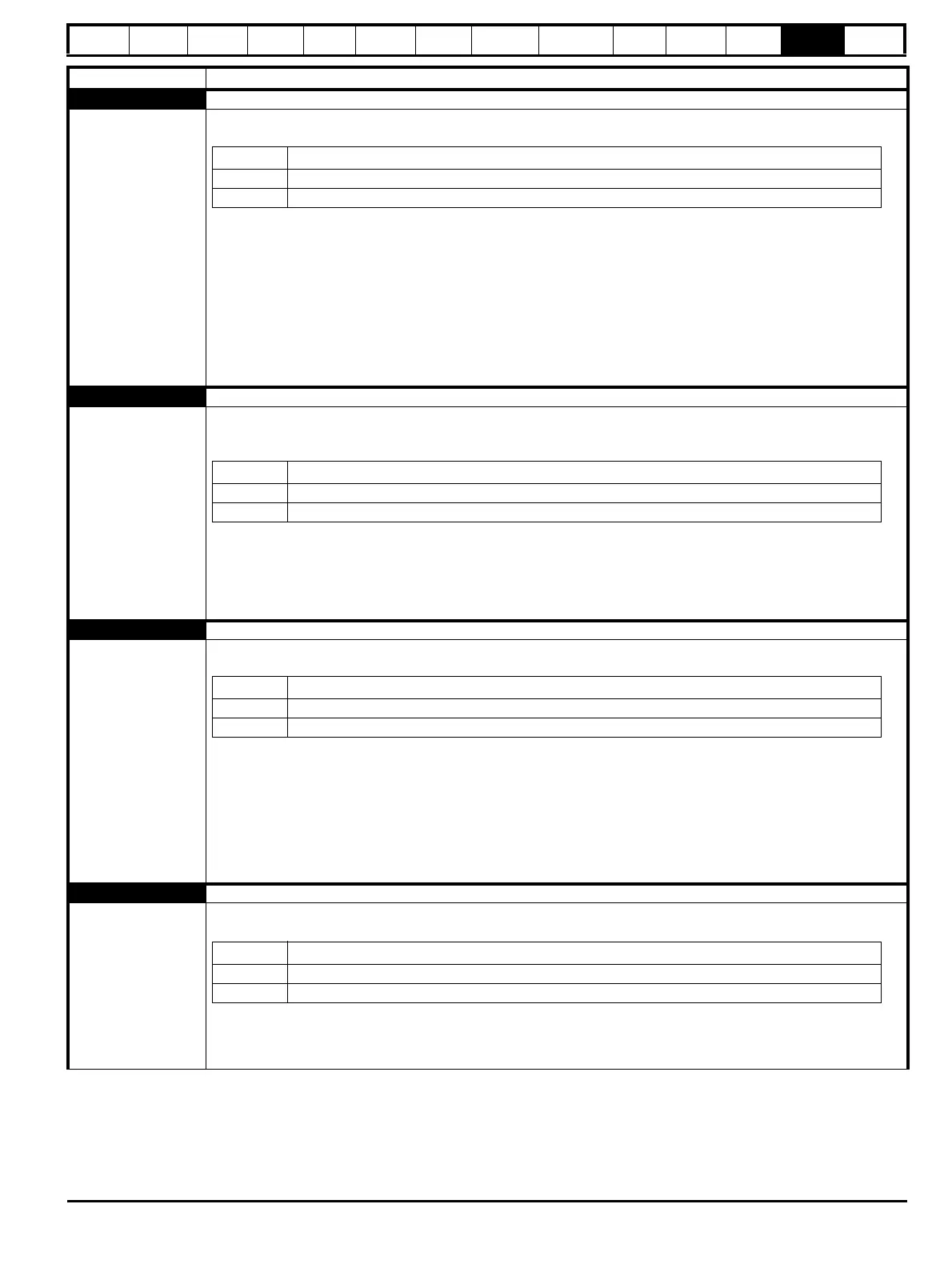
Encoder 3 Phase offset incorrect while running
191
The Encoder 3 trip indicates that the drive has detected an incorrect UVW phase angle while running (RFC-S mode only) or
SINCOS phase error. The feedback device which has caused the trip can be identified by the sub-trip number.
Recommended actions:
• Check encoder shield connections
• Ensure the encoder cable is one uninterrupted cable
• Check the encoder signal for noise with an oscilloscope
• Check the integrity of the encoder mechanical mounting
• For a UVW servo encoder, ensure that the phase rotation of the UVW commutation signals is the same as
• the phase rotation of the motor
• For a SINCOS encoder, ensure that motor and incremental SINCOS connections are correct and that for forward
rotation of the motor, the encoder rotates clockwise (when looking at the shaft of the encoder)
• Repeat the offset measurement test
Encoder 4 Feedback device comms failure
192
The Encoder 4 trip indicates that the encoder communications has timed out or the communications position
message transfer time is too long. This trip can also be caused due to wire break in the communication channel between
the drive and the encoder. The feedback device which has caused the trip can be identified by the sub-trip number.
Recommended actions:
• Ensure the encoder power supply setting (Pr 03.036) is correct
• Complete encoder auto-configuration (Pr 03.041)
• Check the encoder wiring
• Replace the feedback device
Encoder 5 Checksum or CRC error
193
The Encoder 5 trip indicates that there is a checksum or CRC error, or the SSI encoder is not ready. The Encoder 5 trip can
also indicate a wire break to a communications based encoder.
Recommended actions:
• Check the encoder cable shield connections
• Ensure the cable is one uninterrupted cable - remove any connector blocks or if unavoidable minimise the length of any
shield pigtails to the connector block
• Check the encoder signal for noise with an oscilloscope
• Check the comms resolution setting (Pr 03.035)
• If using a Hiperface, EnDat encoder or BiSS encoder carry out an encoder auto-configuration (Pr 03.041 = Enabled)
• Replace the encoder
Encoder 6 Encoder has indicated an error
194
The Encoder 6 trip indicates that the encoder has indicated an error or that the power supply has failed to an SSI encoder.
The Encoder 6 trip can also indicate a wire break to an SSI encoder.
Recommended actions:
• For SSI encoders, check the wiring and encoder power supply setting (Pr 03.036)
• Replace the encoder / contact the supplier of the encoder
Trip Diagnosis
Sub-trip Reason
1 Drive position feedback interface 1
2 Drive position feedback interface 2
Sub-trip Reason
1 Drive position feedback interface 1
2 Drive position feedback interface 2
Sub-trip Reason
1 Drive position feedback interface 1
2 Drive position feedback interface 2
Sub-trip Reason
1 Drive position feedback interface 1
2 Drive position feedback interface 2

 Loading...


